Water-proof Network Dome Camera User Manual Please read this instruction carefully for correct use of the product and preserve it for reference purposes
PROVISION-ISR DAI-390IPVF User Manual 1080P IR Anti-Vandal Vari-Focal IP Dome Camera For H.
Cautions Before operation, we strongly advise users to read this manual and keep it properly for using later. Please use the specified power supply to connect. Avoid from in correct operation, shock vibration, heavy pressing which can cause damage to product. Do not use corrosive detergent to clean main body of the camera. If necessary, please use soft dry cloth to wipe dirt; for hard contamination, use neutral detergent. Any cleanser for high grade furniture is applicable.
Contents 1 2 3 4 5 Introduction .................................................................................................. 1 1.1 Overview ................................................................................................ 1 1.2 Package................................................................................................... 1 1.3 Installation .............................................................................................. 1 1.4 Interfaces and Connections.....
.4.2 Motion Detection Trigger ........................................................ 18 5.4.3 Motion Detection Schedule ..................................................... 19 5.4.4 Alarm Input Trigger ................................................................. 20 5.4.5 Alarm Input Schedule .............................................................. 20 5.4.6 Alarm Out ................................................................................ 21 5.5 Network Configuration ..................
C Chhaapptteerr 11 IInnttrroodduuccttiioonn 1 Introduction 1.1 Overview This IP-CAMERA (short for IP-CAM) is designed for high performance CCTV solutions. It adopts state of the art video processing chips. It utilizes most advanced technologies, such as video encoding and decoding technology, complies with the TCP/IP protocol, SoC, etc to ensure this system more stable and reliable. This unit consists of two parts: the IP-CAM device and central management software (short for CMS).
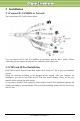
C Chhaapptteerr 11 IInnttrroodduuccttiioonn Step 2: Install the installation dish on the ceiling and then mount the dome on the installation dish by tightening the screws at the bottom of the dome camera as shown in the following figure on the right. Step 3: Adjust the view angle for your need when you view the video on the monitor (If your device cannot support focusing function, please skip this step). Step 4: Tighten the screws and install the back box.
C Chhaapptteerr 11 IInnttrroodduuccttiioonn DC12V:Power supply port. LAN:Network port. It supports PoE power supply. Alarm NO/COM: Alarm output. Conect to alarm output devices. Alarm GND: Connect to external sensor together with the alarm in line. Alarm IN: Connect to alarm input devices, like senor, together with alarm GND line. RS485:Connect to keyboard or speed doom. Connections of the internal ports You shall take down the back box of the device if you want to see the above ports.
C Chhaapptteerr 22 IInnssttaalllaattiioonn 2 Installation 2.1 Connect IP-CAMERA to Network The connection of IP-CAM is shown below: User can connect the PC and IP-CAMERA in accordance with the above picture. Before connecting, please connect external devices, and then connect the power. 2.2 CMS and IP-Tool Installation Find CMS software from CD and then double click “Setup.exe” file to pop up installation wizard. Install the software according to the prompts in the wizard.
C Chhaapptteerr 33 IIE EC Coonnnneeccttiioonn 3 IE Connection User can connect IP-CAM through LAN or WAN. Here only take IE browser (6.0) for example. The details are as follows. 3.1 LAN In LAN, there are two ways to access IP-CAM:①Access through IP-Tool;②Directly Access through IE Browser. 3.1.1 Access through IP-Tool Step 1: Make sure the PC and IP-Cam are connected to the LAN and the IP-Tool is installed in the PC from the CD. Step 2: Use IP-Tool to modify the network of IP-Cam.
C Chhaapptteerr 33 IIE EC Coonnnneeccttiioonn For example, the network segment of this computer is 192.168.13.57. So, please modify the IP address, Subnet Mask, Gateway of IP-Cam which must be in the same network segment with the computer. After modifying, please input the user name and password and then click “OK” button to save the setting. Note: The default user name is: admin. The default password is: 123456. The new IP address of this device will display as follows after modification.
C Chhaapptteerr 33 IIE EC Coonnnneeccttiioonn Input User name and password and then click “OK” button to login. Note: User also can use the modified IP address of the IP-Cam. Input the IP address in the IE browser bar and then click “Enter” to access IP-Cam. The default user name is admin. The default password is 123456. 3.1.2 Directly access through IE The network service is default as shown below: IP address: 192.168.226.201 Subnet Mask: 255.255.255.0 Gateway: 192.168.226.
C Chhaapptteerr 33 IIE EC Coonnnneeccttiioonn Step 2: Open the IE Browser and input the default address of IP-CAM and confirm. Then the IE browser will download Active X control automatically. Step 3: After downloading Active X control, the login dialog box will pop up as below: Step 4: Input user name and password in the login dialog box and click “OK” button to enter into the live interface. You can manage and setup the IP-CAM, such as change IP address etc. 3.
C Chhaapptteerr 44 R Reem moottee P Prreevviieew w 4 Remote Preview 4.1 Remote Preview After you log in, you will see the following window. The descriptions of the icon on the remote preview interface: Icon Description Sensor alarm indicator icon Icon Description Full screen Motion alarm indicator icon Fix size Actual size Start/Stop record Playback Snap Zoom in Talk Zoom out Open/close audio Right click mouse to appear a pull-down list as shown above: Stream: Two streams can be selected.
C Chhaapptteerr 44 R Reem moottee P Prreevviieew w Click PTZ extended button to unfold PTZ control panel. The descriptions of the control panel are as follows: Button Description to rotate the dome upwards; to rotate the dome towards left; right; to rotate the dome downwards; to rotate the dome towards to stop rotating the dome. Drag the scroll bar to adjust rotating speed of the dome. Focus button. Click button to have long focus and click have short focus so that you can adjust the image clearly.
C Chhaapptteerr 44 R Reem moottee P Prreevviieew w User can snap multiple pictures. Select the picture number from Frame pull down list box, such as 2, and check “Title” and “Time” to show capture title and time on the snap pictures simultaneously. Click “Browse” to set saving path; Click “Save” to save pictures to HDD on the computer; Click “Printer setup” to set the printer and print the snap pictures; drag the scroll bar to view all snapped pictures.
C Chhaapptteerr 55 R Reem moottee C Coonnffiigguurraattiioonn 5 Remote Configuration Functions of remote configurations include: System Configuration, Video Configuration, PTZ Configuration, Alarm Configuration, Network Configuration and Advanced Configuration. You should firstly select the menu on the left, and then setup the relative parameters. When one user configures parameters of a certain device, other users can not setup this device. 5.
C Chhaapptteerr 55 R Reem moottee C Coonnffiigguurraattiioonn 2. Select “Modify Time ", user can self-define time. Choose the right "Time Zone" according to user’s location. 3. User can also enable DST and set DST mode and time. 4. User can setup time by select the “Synchronize with NTP Server”. 5. Press the "Save" button to save the settings. 5.1.3 SD Card Setting steps: 1. Enter into "System Configuration" “SD Card” as shown below: Click “Format SD card” to format SD card.
C Chhaapptteerr 55 R Reem moottee C Coonnffiigguurraattiioonn 5.2 Video Configuration Camera Configuration includes four submenus: Camera Configuration, Video Stream, Time Stamp and Video Mask. 5.2.1 Camera Configuration Setting steps: 1. Enter into "Video Configuration " "Camera" interface as shown below: 2. Adjust Brightness, Contrast, Hue and saturation of the picture. 3. Select white balance mode. 4. Sharpen, denoise, frequency, CVBS format and day-night are adjustable. 5.
C Chhaapptteerr 55 R Reem moottee C Coonnffiigguurraattiioonn Here you can set date format and the position of the time stamp shown in the live image. 5.2.4 Video Mask You can set 4 mask area at most. Enable the mask, select color and transparent of the mask area and then drag the mouse to set the mask area. This will take you see a gridding area. After that, click “Save” button to save the settings. Then you will see a mask area on the live image. 5.
C Chhaapptteerr 55 R Reem moottee C Coonnffiigguurraattiioonn 2. Tick off “Enable/Disable PTZ Config”, and then reboot IE client side, the PTZ control panel will be displayed on the live interface. 3. Select the protocol of the PTZ device at the "Protocol" pull down list. 4. Input address of the PTZ in the "Address" textbox. 5. Select baud rate of the PTZ in the "Baud rate" pull down list. For the settings of protocol, address and baud rate please refer to the user manual of the PTZ setting. 5.3.
C Chhaapptteerr 55 R Reem moottee C Coonnffiigguurraattiioonn 2. Input the preset number and set its position by controlling PTZ control panel and then click Add button to add preset point into the Available position list. 3. Select the preset in the pull down list of the Available position and click Go to button to move the dome to this preset point; click Delete button to delete checked preset point. 4. After finishing setting, click Save button to save the settings 5.3.
C Chhaapptteerr 55 R Reem moottee C Coonnffiigguurraattiioonn 5.4 Alarm Configuration Alarm configuration includes six submenus: Motion Detection Area, Motion Detection Trigger, Motion Detection Schedule, Alarm Input Trigger, Alarm Input Schedule and Alarm Out. 5.4.1 Motion Detection Area 1. Enter into “Alarm configuration""Motion Detection Area" to see a interface as shown below: 2. Move the "Sensitivity" scroll bar to setup the motion trace sensitivity. 3.
C Chhaapptteerr 55 R Reem moottee C Coonnffiigguurraattiioonn 2. Check "Enable alarm" check box. Then motion based alarm is activated. 3. Set alarm holding time. 4. Set alarm trigger options. Alarm Out: If selected, this would trigger the external relay output on detecting a motion based alarm. Trigger Snap: If selected, the system will snap images on an alarm and save them in SD card.
C Chhaapptteerr 55 R Reem moottee C Coonnffiigguurraattiioonn 1. Select a date at the "Date" pull down list, press "Add" button to add that date to the list box on the right side and then move the scroll bar to set the schedule of that day. 2. Select a date in the list box on the right side, and press "Erase" to remove the schedule on that day. Press the "Save" button to save the settings. Holiday schedule is prior to Week schedule. 5.4.4 Alarm Input Trigger 1.
C Chhaapptteerr 55 R Reem moottee C Coonnffiigguurraattiioonn 5.4.6 Alarm Out 1. Enter into “Alarm configuration""Alarm output" as shown below: 2. Select alarm holding time and alarm name at the "Alarm out” and “Alarm holding time” pull down list box respectively. 3. Press the "Save" button to save the settings 5.5 Network Configuration Network configuration includes ten submenus: Port, Wired, NET Traversal Configuration, Server Configuration, IP Notify, DDNS Config, RTSP, UPNP, Mail Setting and FTP.
C Chhaapptteerr 55 R Reem moottee C Coonnffiigguurraattiioonn 2. Input port number for IE access in the "HTTP Port" textbox. 3. Input the port number for audio & video transmission in the "Data Port" textbox. 5.5.2 Wired 1. Enter into "Network Configuration""Wired" to see a tab shown below: 2. There are two Options for setup IP: obtain an IP address auto by DHCP protocol and use the following IP address, user can choose one of options for requirements. 3.
C Chhaapptteerr 55 R Reem moottee C Coonnffiigguurraattiioonn 2. Check “transit enable”. Then save the setting. 3. Input www.upnpicp.com in IE address; download and install Active X. Then a window shows up as below: 4. Input the only device ID of the IP-CAM or user-defined name. And then input user name and password. 5.5.4 Server Configuration Enter into “Network Configuration” “Server Config”. 1. Check “Do you want IP Camera to connect Server. 2.
C Chhaapptteerr 55 R Reem moottee C Coonnffiigguurraattiioonn Click “save” button to save the settings. 5.5.5 IP Notify 1. Enter into “Network Configuration””IP Notify” to see a tab as below. 2. If the “Enable notifying change of IP” is selected, when the IP address of the device is changed, a new IP address will be sent to the appointed mailbox automatically; If “FTP” is selected, when the IP address of the device was changed, a new IP address will be sent to FTP server. 5.5.6 DDNS Configuration 1.
C Chhaapptteerr 55 R Reem moottee C Coonnffiigguurraattiioonn 2) Fill in the registration form, then click "Submit" 3) Fill in the host name you want to apply for and press "Request Domain" (for example "home") 4) If there is no problem with the domain registration you will see the following message: “Your domain was successfully created.
C Chhaapptteerr 55 R Reem moottee C Coonnffiigguurraattiioonn 1. Enter into "Network Configuration""DDNS Configuration" tab as below: Note: The steps to band a domain name for video surveillance server are as follows. Firstly, register a user name and a password to log on the website of service supplier, and then apply for a domain name online for the server. After that, users can visit the server through inputting the domain name at IE terminal. 2. Press the "Save" button to save the settings.
C Chhaapptteerr 55 R Reem moottee C Coonnffiigguurraattiioonn Step 2: Click to enter the website. Step 3: Click "New User" in the right of homepage to register. For example: User ID is ‘abc’, and password is ‘123456’. The register dialog display as above. (2) Login Step 1: Return to homepage after registering successfully. Step 2: Click "Account Manager" on the right of homepage to login. Step 3: Input the username and password with the information that you have registered.
C Chhaapptteerr 55 R Reem moottee C Coonnffiigguurraattiioonn 3. Application Connect IP-CAMERA to the Network Client. Step 1: After popping up the login interface, fill in "Server" textbox with ‘*.dns2p.com’ to visit the Network Client of the IP-CAMERA. The domain set in ‘(3) Domain Setup’. According to the example above, fill in "Server" textbox with ‘IP-CAMERA.dns2p.com’. Step 2: Click "save" button to save the above setting. 5.5.
C Chhaapptteerr 55 R Reem moottee C Coonnffiigguurraattiioonn components, the UPnP icons will display. Users can double-click certain icon to connect the remote surveillance login interface through IE. If “Show icons for networked UPnP devices” can’t display in the “Network Tasks” list box, please follow the below operation: Click “Tools”-- “Folder options” Check the “Show common tasks in folders” in the “Tasks” check box, UPnP icon will display. 5.5.
C Chhaapptteerr 55 R Reem moottee C Coonnffiigguurraattiioonn 7. After all parameters setup, user can click “Test your account settings”. If email sent successful, a “Test Successful” window will pop up, if not, users can try other email addresses or check the setting. Note: If you change the static IP into PPPoE and select mailbox, there will be an e-mail sent to users’ mail box for notifying a new IP address. 5.5.10 FTP Enter into Network ConfigurationFTP interface; please refer to below picture.
C Chhaapptteerr 55 R Reem moottee C Coonnffiigguurraattiioonn Add user: 1. Clicking "Add" button pops up "Add user" dialog box as shown below: After binding physical address to the IP-CAM, you can access the device on this PC only. If the MAC address was ““00:00:00:00:00:00” which means it can be connected to any computers. 2. Input user name in "User Name" textbox (only letters). 3. Input characters in "Password" and "Confirm Password" textbox (letters or numbers). 4.
C Chhaapptteerr 55 R Reem moottee C Coonnffiigguurraattiioonn MAC” text box. 6. Click “OK” button to modify user’s password and binding MAC address successfully. Delete user: 1. Select the user which needs to delete in the user configuration list box. 2. Clicking “Delete” button will pop up a confirm dialog box. Then click “OK” to delete the user. Note: The default super administrator cannot be deleted.
C Chhaapptteerr 55 R Reem moottee C Coonnffiigguurraattiioonn click “delete” button to delete that MAC address. 5. Click "save" button to save the above setting. 5.6.4 Configure Backup & Restore Enter into Advanced configurationConfigure Backup & Restore Interface. Import & Export Configuration: User can import or export the setting information from PC or to device. 1. Click “Browse” to select save path for import or export information on PC. 2.
C Chhaapptteerr 55 R Reem moottee C Coonnffiigguurraattiioonn 5.6.6 Upgrade Enter into Advanced Configuration—Upgrade interface. 1. Click “Browse” button to select the save path of the upgrade file 2. Click “Upgrade server firmware” button to start upgrading the application program 3. The device will restart automatically 4. After you successfully update the software, click “OK” button to close IE and then re-open IE to connect IP-Cam.
C Chhaapptteerr 66 V Viiddeeoo S Seeaarrcchh 6 Video Search Click “Picture” button and search the images which saved in the TF card. 1. Select date in the “calendar”, check “motion detection” relatively and click “search” button. Then the triggered snap pictures will be displayed in the list box. 2. Double click a filename or select a filename and then click “view” button in the list box to view snap pictures.
C Chhaapptteerr 66 V Viiddeeoo S Seeaarrcchh Item 1 Buttons Explanations Close: Select certain picture and click this button will close this preview picture.
C Chhaapptteerr 88 IIP P--TTooooll 7 Mobile Surveillance This IP-CAM supports mobile surveillance by phones with Windows mobile, iPhone, Android and Blackberry OS. Please check the operation system version of mobile before use; and connect the IP-CAM to Internet. 7.1 Network Configuration Access device via LAN Step 1: Connect device via wireless router. Then checkmark DHCP both in router and device to automatically acquire IP address or enter the IP address manually.
C Chhaapptteerr 88 IIP P--TTooooll 7.2 By Phones with iPhone OS • Install through Iphone. Step 1: Open App Store software as shown in the figure on the left. Step2: Search “Provision Cam” and click “Free” button as shown in the figure on the right. Step 3: Click “Install App” button as shown in the figure on the left. Step 4: Input iTunes Store password and then click “OK”. The software will be installed automatically. • Install Software through PC Step 1: Install iTunes store in PC and then login.
C Chhaapptteerr 88 IIP P--TTooooll "Provision Cam" Instruction • 1. Login Step 1: Choose network type. There are two network connection ways: 3G/3G +WIFI, enhanced video quality. This network supports main stream and sub stream. The real-time image will be displayed by using sub stream. 3G, normal video quality compared to the former network type. Step 2: Input server, account and password. Server: WAN IP address (or domain name) plus HTTP port of the device. For example: 210.21.183:89 or 123.dvrdydns.
C Chhaapptteerr 88 IIP P--TTooooll information, device information, network information, etc. :Server list button. Click this button to add server list. :Help button. Help you know about the use of this software quickly. :CMS button. Make you preview the live image of multi-devices. :Log off button. Click this button to return to the login interface. :Screen mode button. You can choose 1,4,6,8,9,13 or 16 screen display mode. :Favorite channel display button.
C Chhaapptteerr 88 IIP P--TTooooll Channel indicator instruction: :Video loss : Schedule recording :Sensor alarm :Motion alarm :Others :Motion /sensor alarm based recording or manual recording 3. Click Server list button to pop up the following picture. Add device: Click “Add” button in the top right corner to pop up a dialog box as shown in the following left picture. Input the relative information of the device and click “Save” button.
C Chhaapptteerr 88 IIP P--TTooooll 1. Click “Screen mode” button to select channel as shown in Fig 1. 2. When there is video playing in a screen, you can switch the channel by long pressing the screen as shown in Fig 2. 3. When no video is playing in a screen, click this screen to choose channel as shown in Fig 3. 4. When the single channel is playing, you can zoom in/out the image by swiping you finger up and down as shown in Fig 4. 5.
C Chhaapptteerr 88 IIP P--TTooooll Fig 4 5. Fig 5 CMS Function This function makes multi-device managements and preview come true. Step 1: Click to enable CMS function. When this icon turns green, it means this function is enabled. Step 2: Click to choose channel as shown in the right picture. After you choose the channel, click “ok”, the system will display the related image automatically. If channels have been added into the group, you can see the images by clicking the group name.
C Chhaapptteerr 88 IIP P--TTooooll Then click button to play. Only one favorite group can be collected. :Color means the channel or group has been collected. Grey means the channel or group isn’t collected. 7. Playback Interface Click “Playback” button to enter the playback interface. Then click “Search” button to search the file. To play the record by click this file name. 8. Click 9. Image View button to view the captured pictures.
C Chhaapptteerr 88 IIP P--TTooooll 7.3 By Phones with Android Software Installation Step 1: Run “Play Store” (or Google market) program. Step 2: Search “Provision Cam”. Step 3: Press “Install” button. Step 4: Install the software subject to the notes. Once the downloading is done, the software will install automatically Login Menu Step 1: Configure the network of your device and mobile phone. Step 2: Input the WAN IP address/domain name and port of your device in the sever column.
C Chhaapptteerr 88 IIP P--TTooooll Step 3: Input the account and password of your device. The default account name is admin and the default password is 123456. Step 4: Check “Remember Server” to save the setting. When you login next time, you can click button to select this server for quick access.
C Chhaapptteerr 88 IIP P--TTooooll Record Playback: Click “Playback” in the main menu interface to enter playback interface. Then choose the channel you want to playback. This will take you to see the record file. Click this file to play. Pause/Play Stop Forward Backward Server List: In the main menu interface, click “Server list” to see the above picture on the left hand. Add Server: Click button to pop up a window as shown in the above picture on the right hand.
C Chhaapptteerr 88 IIP P--TTooooll Favorite Channel: Check the favorite channels and click “Save” button to save these channels. Then go into live interface and click button to play these favorite channels. Storage: Setup the relevant parameters of mobile video. Information View: view the DVR/NVR basic information as shown in the picture on the right.
C Chhaapptteerr 88 IIP P--TTooooll 8 IP-Tool Updating through IP-Tool Note: Do not cut off power supply and internet when updating. If the device is unable to start because of the failure of upgrade, it needs to retrofit. to run this Acquire the IP-Tool from the supplier and then double click the IP-Tool icon software. Then the device can be searched; if the device can’t be searched, please check whether the PC and the device connect to the network or not.
C Chhaapptteerr 88 IIP P--TTooooll Modify IP address and click OK button to exit the dialog box. After that, IP-Tool will display the new IP address. Upgrade Software Select the device; right click “Update software”. Click “Update” to start upgrading,the progress bar will display as below. When upgrading, please do not disconnect PC and the device and make sure the power is on.
C Chhaapptteerr 88 IIP P--TTooooll Input the relevant information and click “Browse” button to choose your update file. After that, click “Update Kernel” button to start updating. When upgrading, do not disconnect PC to device and make sure the power is on. The update progress bar will display as below: After finishing upgrading, a message box will pop up. After a while, the device will restart automatically.
C Chhaapptteerr 99 Q Q& &A A 9 Q&A 1. Q: How to find my password if I forget it? A:Joint the default line and GND line to reset. Default IP: 192.168.226.201 User name: admin Password: 123456 2. Q:Fail to connect devices through IE browser, why? A: Network doesn’t connect well. Please check the connection and make sure it connected well. B: IP is not available. Reset the valid IP. C: Web port number has been revised: contact administrator to get the correct port number. D: Exclude the above reasons.
C Chhaapptteerr 99 Q Q& &A A Fig 4-1 Fig 4-2 ④then click ok to finish setup. b. Other plug-ins or anti-virus blocks ActiveX. Please uninstall or close them. 5. Q:No sound can be heard, why? A:Without connect audio input device. Please connect and try again. B: Without enable audio function at the corresponding channel. Please check AUDIO item to enable this function. 6. Q:Why doesn’t the device connect to wireless? A: Check the statues of wireless router.
C Chhaapptteerr 1100 S Sppeecciiffiiccaattiioonn 10 Specification Model Image Sensor Effective Pixels Electronic Shutter Day & Night Min.
C Chhaapptteerr 1100 S Sppeecciiffiiccaattiioonn Notes: IP-CAMERA User Manual - 55
C Chhaapptteerr 1100 S Sppeecciiffiiccaattiioonn IP-CAMERA User Manual - 56