Table of Content: Chapter 1: Product Summary: 1.1 Technical Parameters…………..………….…………….…………….2 1.2 Package Contents….………………………………………….……….3 1.3 Function description………………………………………….……….3 Chapter 2: Equipment installation: 2.1 DIP switch settings…………………................................................5 2.2 Dome camera structure diagram……………………………….……7 2.3 Bracket installation diagram...……………………………………….8 Chapter3: System OSD menu settings: 3.1 Power-on self-test………….……………..………………………..….8 3.
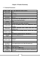
Chapter 1:Product Summary: 1.1 Technical Parameters: Model number 4" High Speed Mini Dome Camera Optical focus 10X Image sensor 1/3"CCD Signal mode PAL/NTSC Resolution Optical focus Presets 650TVL Manual/Auto, high performance DSP to utilize high continuous focusing function. 256 Pattern scan 4groups,each can record 100 actions Cruise scan Up to 30 presets cruise with independent dwell duration.
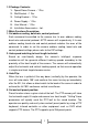
1.2 Package Contents: 1. Speed Dome Camera – 1 Pcs 2. Wall Bracket – 1 Pcs 3. Ceiling Bracket – 1 Pcs 4. Power Supply – 1 Pcs 5. User Manual – 1 Pcs 6. Installation Accessories – Lot. 1.3Main Functions Description: 1. Set address coding, baud rate, control protocol: Each command transmitted to the camera has its own address coding, baud rate and control protocol. APTZ camera will respond only if its own address coding, baud rate and control protocol matches the ones of the command.
6. Lens Control: (1) Zoom control Users can control the PTZ lens in order to adjust the zoom level of the camera and get wide/narrow view according to the scene. (2) Focus Control System default is auto-focus. The object in center of the screen will be the subject of focus. In exceptional circumstances the user can manually adjust the focus in order to maintain a clear picture.
10. Night Mode (color / Black & White conversion): Cameras with night mode, automatic color / monochrome conversion mode, in accordance with changes in ambient light automatic conversion CCD illumination. Such as: adequate lighting during the day due to the use of general illumination to ensure colorful images. In the night illumination can be automatically changed to black and white images show a clear interest. 11. Cruise: Cruise can be built from several preset points.
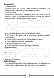
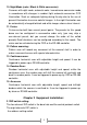
DIP switch to “ON” means to “1”,DIP switch to "OFF" means "0". The baud rate and control protocol as the following table: NO. Baud rate (BPS) 1 2 3 OFF OFF PELCO-P ON OFF PELCO-D OFF ON PELCO-D/P ON ON PELCO-D/P Control Protocol 4 OFF OFF 9600 ON ON 9600 OFF ON 4800 ON OFF 2400 8-bit DIP switch is used to set the camera's address coding. Address set binary mode can be set to a total of 256 different dome camera address coding, see coding table address.
248 OFF OFF OFF ON 7 ON ON ON ON
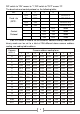
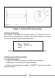
2.2 Dome camera structure diagram: Figure 1 Figure 2 2.
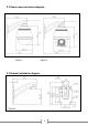
Figure 4 Chapter 3 System OSD menu settings: 3.1Power-On Self-Test: When power is connected to the dome camera, the camera will move in horizontal and vertical directions to confirm that motors and belts are in order. The screen will show system-related information. PTOL: PELCO-D COMM: 2400,N,8,1 ADDR: 1 Display: PELCO-D protocol、Baud Rate 2400、Address code 1 3.2Preset point setting and calling: 3.2.1 Set Preset points: (1) Make sure the correct camera is selected in your controller.
3.2.2 Call preset points: (1) Make sure the correct camera is selected in your controller. (2) Press the required preset number (inputs the designated preset) + PREVIEW* button, the camera will immediately move to the desired preset position.
3.4OSD Main Menu Once the dome camera is power on and finished self-testing, call preset 95in order to access the ODS main menu as shown in Table 3.1. MAINMENU SYSTEM INFORMATION Menu function descriptions Displays camera basic information. See More Details in section 3.5. ADDR SETTING Used to set the camera address. See More Details in section 3.6. MOTION “PTZ” setup menu. See More Details in section 3.7. PATTERNS Pattern scan setting. See More Details in section 3.8. CAMERA Lens setting.
3.5 SYSTEM INFORMATION: SYSTEM INFORMATION Menu function descriptions Serial information, display the dome camera serial port baud rate, parity, data bits, stop bits of information. COM 2400,N,8,1 ADDRESS 1 Display the current dome camera address Display the current dome camera communication protocol. PROTOCOL PELCO-D Display the current dome camera preset number. PRESETS 256 SOFTWARE VERSIONV#.# Display the current software version. BACK Return to main menu. EXIT Exit the menu setting.
3.7 MOTION (PTZ) Settings: This menu is used to set PTZ parameters such as movement and orientation angles as shown in the following table: MOTION Menu function descriptions SET FRAME SCAN Set the scan left and right limits. See More Details in section 3.7.1. POWER UP NONE Power on setting menu. See More Details in section 3.7.4. PARK TIME Waiting time before performing idle action. 15S Which action to perform when the dome camera is idle. See More Details in section 7.4.5.
3.7.4POWER UP Settings: This will define which action the dome camera will perform when it is powered on. (unless any other action was received). Parameters in the following table: POWER UP Menu function descriptions NONE Don’t perform any action. AUTO SCAN Perform continuous scanning action. RANDOM SCAN FRAME SCAN Perform random scanning action. Perform frame scan action* PRESET 1 Send the camera to Preset No.1 PRESET 8 Send the camera to Preset No.
3.8PATTERNS Menu: PATTERNS PATTERNNUMBER 1 PROGRAM PATTERN CLEAR CURRENT PATTERN CLEAR ALL PATTERN Menu function descriptions Select pattern number, within 1~4. To select pattern scan line; Operations shown in section 3.8.1. Clear current pattern scan line. Clear all the pattern lines. BACK Return to the previous menu. EXIT Exit the menu setting. 3.8.
3.
EXIT Exit the menu setting. *in case you are setting-up the cruise using Provision-ISR DVR, make sure that you mark “Simulative Cruise” as active. Otherwise, the cruise may not work. 3.11 IR Settings (Only Applicable in IR Dome Cameras) IR SETTING Menu function descriptions IR MODE AUTO ON:IR light is forced to be on constantly; OFF: Infrared light is forced to be off constantly; AUTO:IR light will switch automatically. IR ON SENS240 Light intensity for IR light to turn on, within 81~254.
Chapter4: Simple troubleshooting and maintenance. 4.1 Simple Troubleshooting Table: Failure Power connected but the camera is not performing self-test, no image Power connected, the camera is performing self-test, image available, but no control Unable to complete self-test, there are images associated with motor tweet sound Image instability Possible Cause Solutions Connected the wrong power cord Check voltage in cable Power supply is damaged Check power ratings. Replace power supply.
Blurry Image Long delays in actions performing / camera going out of control. Manual focus on the state Make sure settings are on auto focus. If so try to shift the camera in any direction to reinstate auto focus mode Power rating is not sufficient Replace power supply to meet the requirements of the power consumption. If the camera is far from the power supply check cables for shortages. RS-485 the signal attenuation Check RS-485 Signal Cable.