(Grouper-GL8E) User Guide Motherboard PTGD1-LA
Contents Checklist PTGD1-LA specifications summary ..................................................... iii ii 1. Motherboard layout ................................................................. 1 2. Central Processing Unit (CPU) ................................................. 2 3. System memory ...................................................................... 4 4. Expansion slots ........................................................................ 6 5. Jumpers ..................
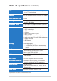
PTGD1-LA specifications summary CPU LGA775 socket for the Intel® Pentium® 4 processor in the 775-land package Chipset Intel® i915G graphics memory controller hub (GMCH) Intel® ICH6 Front Side Bus (FSB) 800MHz Memory 4 x 184-pin DDR DIMM sockets for up to 4GB non-ECC DDR SDRAM Expansion slots 1 x PCI Express x16 graphics connector (PEG slot) 3 x PCI slots Onboard I/O 1 x Parallel port (ECP, EPP) 1 x PS/2 keyboard port 1 x PS/2 mouse port 1 x VGA port 1 x RJ-45 Fast Ethernet LAN port 1 x IEEE 1394
iv
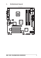
1. Motherboard layout 24.5cm (9.6in) PS/2KBMS T: Mouse B: Keyboard 4Mbit Flash ROM CLPWD Top:Line In Center:Line Out Below:Mic In Top: Subwoofer Speaker Out Center Rear Speaker Out Below Side Speaker Out FLOPPY IDE Intel i915G GMCH PCIEX16 24.5cm (9.6in) AUDIO CPU_FAN SYS_FAN ATX12V ATX Power Connector USB2.
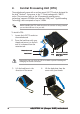
2. Central Processing Unit (CPU) The motherboard comes with a surface mount LGA775 socket designed for the Intel® Pentium® 4 processor in the 775-land package with 1MB L2 cache. The processor, built on the 90-nanometer manufacturing technology, supports 800MHz front side bus (FSB), Intel® Hyperthreading Technology, and core speeds of up to 3.4GHz. Before installing the CPU, make sure that the cam box is facing towards you and the load lever is on your left. To install a CPU: 1.
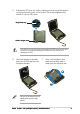
5. Position the CPU over the socket, making sure that the gold triangle is on the bottom-left corner of the socket. The socket alignment key should fit into the CPU notch. Alignment key Gold triangle mark The CPU fits in only one correct orientation. DO NOT force the CPU into the socket to prevent bending the connectors on the socket and damaging the CPU! 6. Use both thumbs to carefully push out the PnP cap from the load plate window. 7.
3. System memory The motherboard comes with four Double Data Rate (DDR) Dual Inline Memory Module (DIMM) sockets. These sockets support up to 4GB system memory using 184-pin unbuffered non-ECC 2.6V DDR SDRAM. DIMM_B2 DIMM_B1 DIMM_A2 DIMM_A1 The following figure illustrates the location of the DDR DIMM sockets.
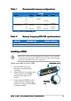
Table 1 Recommended memory configurations Sockets Mode Single-channel (1) DIMM1 DIMM2 DIMM3 DIMM4 Installed — — — (2) — Installed — — (3) — — Installed — — (4) Dual-channel* — — Installed (1) Installed — Installed — (2) — Installed — Installed (3) Installed Installed Installed Installed * Use only identical DDR DIMM pairs.
4. Expansion slots The motherboard has one PCI Express and three PCI slots. To install and configure an expansion card: 1. Install an expansion card following the instructions that came with the chassis. 2. Turn on the system and change the necessary BIOS settings, if any. 3. Assign an IRQ to the card. Refer to the tables below. 4. Install the drivers and/or software applications for the expansion card according to the card documentation.
IRQ assignments for this motherboard A B C D E F PCI slot 1 — — — shared — — PCI slot 2 shared — — — — — PCI slot 3 — used — — — — PCI slot 4 — — — shared — — PCI slot 5 shared — — — — — Onboard LAN — — — — — used Onboard 1394 controller — — — — used — PCI Express slot This motherboard has one PCI Express slot, which supports a 164-pin x16 interface graphics card. PCI slots There are three 32-bit PCI slots on this motherboard.
5. Jumpers Clear RTC RAM (3-pin CLRTC) This jumper allows you to clear the Real Time Clock (RTC) RAM in CMOS. You can clear the CMOS memory of date, time, and system setup parameters by erasing the CMOS RTC RAM data. The onboard button cell battery powers the RAM data in CMOS, which include system setup information such as system passwords. To erase the RTC RAM: 1. Turn OFF the computer and unplug the power cord. 2. Move the jumper cap from pins 2-3 (Normal) to pins 1-2 (Clear CMOS).
6. Connectors 6.1 Rear panel connectors 1 2 3 4 5 6 7 8 9 10 16 1. 2. 3. 4. 5. 6. 7. 8. 9. 15 14 13 12 11 P S / 2 m o u s e p o r t . This green 6-pin port is for a PS/2 mouse. P a r a l l e l p o r t . This 25-pin port connects a parallel printer, a scanner, or other devices. I E E E 1 3 9 4 p o r t . This 6-pin IEEE 1394 port provides high-speed connectivity for audio/video devices, storage peripherals, PCs, or portable devices. R J - 4 5 p o r t .
Audio 2, 4, 6, or 8-channel configuration Headset/ 2-channel 4-channel 6-channel 8-channel Line In Line In Line In Line In Lime Line Out Front Speaker Out Front Speaker Out Front Speaker Out Pink Mic In Mic In Mic In Mic In - - Center/Subwoofer Center/Subwoofer Black - Rear Speaker Out Rear Speaker Out Rear Speaker Out Gray - - - Side Speaker Out Light Blue Yellow Orange 1 1 . U S B 2 . 0 p o r t s 3 a n d 4 .
6.2 Internal connectors This section describes and illustrates the internal connectors on the motherboard. 1 . Floppy disk drive connector (34-1 pin FLOPPY) This connector supports the provided floppy drive ribbon cable. After connecting one end to the motherboard, connect the other end to the floppy drive. (Pin 5 is removed to prevent incorrect insertion when using ribbon cables with pin 5 plug). PIN 1 FLOPPY NOTE: Orient the red markings on the floppy ribbon cable to PIN 1.
3. ATX power connectors (24-pin ATXP WR ATXPW R,, 4-pin ATX12V) These connectors are for an ATX 12V power supply. The plugs from the power supply are designed to fit these connectors in only one orientation. Find the proper orientation and push down firmly until the connectors completely fit. In addition to the 24-pin ATXPWR connector, this motherboard requires that you connect the 4-pin ATX +12V power plug to provide sufficient power to the CPU.
IEEE 1394 connector (10-1 pin FRONT_1394) This connector is for a 10-to-6-pin 1394 serial connector cable that connects to a 1394 module. Attach the 10-1 pin cable plug to this connector, and the 6-pin cable plug to the 1394 module. You can also connect a 1394-compliant internal hard disk to this connector. +12V TPB+ GND TPA+ 5. PTGD1-LA PTGD1-LA FRONT_1394 Connector 6.
DIMM_B2 DIMM_B1 DIMM_A2 DDR DIMM connectors (184-pin DIMMA1, DIMMA2, DIMMB1, DIMMB2) These four 184-pin DIMM sockets support up to 4GB system memory using unbuffered ECC PC3200/2700/2100 DDR DIMMs. DIMM_A1 7. PTGD1-LA PTGD1-LA 184-Pin DDR DIMM Sockets 8. Fan connectors (3-pin SYS_FAN, 4-pin CPU_FAN) The fan connectors support cooling fans of 350mA~740mA (8.88W max.) or a total of 1A~2.22A (26.64W max.) at +12V.
Internal audio connectors (4-pin CD-IN, F_LINE_IN) These connectors allow you to receive stereo audio input from sound sources such as a CD-ROM, TV tuner, or MPEG card. PTGD1-LA PTGD1-LA Internal Audio Connectors Right Audio Channel Ground Ground Left Audio Channel CD_IN (Black) F_LINE_IN (White) Right Audio Channel Ground Ground Left Audio Channel 9. 1 0 .
AUD_FPOUT_L AUD_MIC_JD AUD_FPOUT_R AUD_MIC2 AUD_MIC1 11. Front headphone connector (10-1 pin FRONT_AUDIO) This connector is for a chassis-mounted front panel headphone port.