CHALLENGER PRO 2 WIRE VIDEO INTERCOM – TECHNICAL GUIDE: APARTMENT APPLICATIONS
CONTENT Section1 - Introduction System Features System Capacity System Extension System Function - - - - - - - - - - - - - 1 - - - - - - - - - - - - - - - - - - - - - - - - - - - - - - - - - - - - - - - - - - Section2 - Units and Installations - -1 -1 -1 -1 4 Door Station - - - - - - - - - - - - - - - - - - - - - - - - - - - - - - - - - - 4 Features - - - - - - - - - - - - - - - - - Parts and functions - - - - - - - - - Place Name Plate - - - - - -
Section3 - Cables and Connections 28 General Rules for Installation - - - - - - - - - - - - - - - - - - - - - -28 Connecting the Connectors Installation Height - - - - - - - Door Station Install Condition Table of Cables and Distance - - - - - - - - - - - - - - - - - - - - - - - - - - - - - - - - - - - - - - - - - - - - - - - 28 - 28 - 28 - 29 System Wirings and Connections - - - - - - - - - - - - - - - - - - -30 1.
Section1 - Introduction System Features • • • • • • • With only 2 wires (no polarity) throughout the whole installation, the 2 -wire CHALLENGER PRO system is a simplified installation system with minimum wiring and powerful features. The minimum wiring drastically reduces installation times and errors. Centralized power supply for the entire system. Use Plug -in connectors and DIP switchers for more easy installation. Flexible cable connection to wire, support in -out, branching and mixed mode.
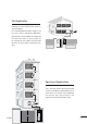
Villa Application CALL CALL UNLO C K UNLO C K TALK/MO N TALK/MO N IN-U SE IN-U SE CALL UNLO C K TALK/MO N IN-U SE Although the CHALLENGER PRO system is mainly designed for the small apartment system usage, it can be used in villa or villa group applications. Multi Monitors can be installed in a family with the same User Code, or many houses can be connected as one system, and all of these Monitors can have calling conversation each other.
Section2 - Units and Installations Door Station Bit-4=off 123 45 6 ON PROR11/ID/D 8 PROR11/D8 PROP11/D24 Bit-4=on 123 45 6 ON Features • • • • • • • • • • • • PROR11/ID/S 4 PROR11/S4 PROP11/S12 Full anodize aluminum panel. SONY color CCD camera. camera angle adjustable. ID card access control Night -view LED with CDS light sensor. Backlit name plate for each button. Use DIP switches for multi Door Station configuration. Direct connect to electronic lock of 12Vdc. Exit button.
Parts and functions Camera Lens CDS Sensor Infrared LED 308 mm Microphone Name plate 298.5 mm Camera Angle adjustment Speaker Speaker Vol adjustment Connection Board Call button 18 mm 123 mm 45 mm 114.5 mm Place Name Plate Press down and shift right/left to open the transparent name plate cover, then insert the name paper, then put the plate cover back to the panel. Note that double button line panel can be opened both direction, single button line can only be opened at the right side.
Standard Installation Camera Angle adjustment 298.5 mm Open the mounting box of the panel, use a cross screw to adjust the view angle of the camera before installation. Installation with expanding panel Jointer*2 L2 1 SET 123456 ON L1 JP-LK CHALLENGER PRO - System T/R T/R+ +12V LK - (GND) LK+(COM) N.O.
T/R - LK - (GND) T/R+ N.O. EB+ EB - PROR11 Connection Board L1 1 2 3 4 5 6 ON L2 RS-485 CN-LK L1 1 2 3 L2 PA 1 2 3 PB SET T/ R+ JP-LK T/R - +12V LK - (GND) LK+(COM) N.O. EB+ EB - SET ON LK+(COM) 12 34 5 6 CN-LK +12V RS-485 Terminal Descriptions BUS PA PB BUS • • • • • • • • • • • • • +12V: 12VDC power output. LK-(GND): power ground. LK+(COM): electronical load activation relay contact common. NO.
DIP Switches settings ONLY APPLICABLE FOR MULTI DOOR STATION Total 6 bits in the DIP switches can be configured. The switches can be modified either before or after installation. • Bit -1 and Bit 2 is for Door Station ID settings, when mutil Door Stations are installed in the system, these two bit ON(1) OFF(0) ON 1 2 3 4 5 6 • • • • = = must be set correctly, the first Door Station set to 00, the second one set to 01, the third one set to 10, the fourth one set to 11.
T/R T/R+ L1 T /R+ (GND) RS-485 CN-LK - JP-LK T /R - + 12V LK LK +(CO M) 1 2 3 4 5 6 E B+ EB - L1 L2 BUS PA 1 2 PA PB SET ON N.O . L2 1 2 3 SET PROR11 Connection Board 1 23456 ON CN-LK +12V LK - (GND) LK+(COM) N.O. EB+ EB - RS-485 Door Station Lock Connections PB 3 BUS 1. Direct lock connection Use the power of the system to supply for the electronic lock, so that the lock can connect to the Door Station directly, without a additional power supply for the electronic lock.
B. Connection for Power - -off -to -Unlock type: DIPS +12V LK - (GND) - + 12 34 56 N.O. EB+ EB - 12V 300mA DIPS-5: set to on, unlocking time is 5 seconds. JP_LK 1 Jumper set to 2-3 position 2 3 set to Normally Closed on the Unlock Relay mode on CHALLENGER PRO software. ON 2. Additional power supply When the electronic lock is over 12 Vdc, additional power supply for the lock is needed. • • • The power supply for the lock must be less than 48Vdc 1.5A.
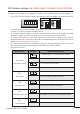
Proximity ID Card Operation • • • • Up to 1000 user cards can be registered by the Door Station. Easy management with LED state and Sound hint. There are two master cards, one MASTER CARD ADD card and one MASTER CARD DELETE card,When adding a new master card, the old one will be replaced automatically. Card reading distance is from 3 to 5 cm. The Master cards are necessary when you add or delete user cards, Please keep the Master cards carefully.
Add user cards by Room: Press a certain button on the Door Station, then show the cards which to be assigned to this Room. Then press an other button and show the cards..... Show the MASTER CARD ADD card in standby Show the MASTER CARD ADD card again to confirm and exit. Delete user cards by Room: Press the button(s) that the cards belong to on the Door Station.
Monitor Features LCD Touch Screen LCD screen Microphone LED Indicator PO W ER IN- U S E + - Speaker CALL + Button UNLOCK - Button CALL button UNLOCK button TA LK/ MON IN-US E MENU Button IN T ER C OM TALK/MON button LED indicator INTERCOM Button U N L OC K UNLOCK Button TAL K/ M ON IT OR TALK/MON Button Microphone Speaker Mounting Hook Ventilation Vent BT1 D IP S BT2 L1 EH ON Mounting Hook Connection Port D IP S ON BT1 Mounting Hook BT2 EH GN D VD 1 2 3 4 5 6 Connection Port L
Terminal Descriptions Monitor Connection Board S1 ON SW+ SWEXT-RING GND VIDEO 123456 • SW+: Door bell call button. • SW-: Door bell call button. • • • EXT-RING: External ringer output(12Vdc 100mA) GND: Ground. VIDEO: Video signal output. BUS • S1: DIP switches for system configurations. • BUS: non -polarity bus line. Intercom function There are three kinds of intercom function available in the CHALLENGER PRO system. 1.
Step 1: Run the CHALLENGER PRO CONFIG software. Connect the USB -485 Convertor to the PROR11 Door Station and the PC, double click the software to make it running on the PC, then click the Namelist tap, the screen will be showed: Step 2: Edit the namelist. In the name input field, there are a Room No. colume and a Name Lable colume, each User Code have a corresponding Room No. and a Name Lable.
Color Picture Memory Total 128 pcs picture can be stored in the Monitor. User can both record the picture manually and set the Monitor to automatically record pictures. • • • • Manually record: when the Monitor is in monitoring or talking state(the screen is turned on), press the record icon on the touch screen or press a record button, the current picture which show on the screen will be saved into the built -in flash memory of the Monitor.
User Code Setup In the CHALLENGER PRO system, every apartment must have a unique identification called User Code. The DIP switches are used to configure the User Code for each Monitor. • • • Bit -1 to Bit -5 are used to User Code setting. The value is from 1 to 32, which have 32 different codes for 32 apartments. When multi Monitors are installed in one apartment, these Monitors have to use the same User Code setting, and the Master/Slave mode should be set on the Monitor.
Monitor Extending Connection POWER IN-US E C ALL + U N LOC K - S1 T ALK/M ON ON IN - U SE INTE RC OM 123 45 6 S1 UNLO CK ON SW+ TALK/ M ONI TO R SW 1 2 3 4 5 6 SW+ SWEXT-RING GND VIDEO EXT-RI NG GND VIDEO L1 L2 B T1 DIP S EH GND 5 6 1 2 3 4 L2 L1 L2 DIPS ON BT 1 BT 2 EH GN D 1 2 3 4 5 6 VD L1 L2 1. Door Bell Call Button Additional door bell call button can be connected to the Monitor, so that the visitors can ring the door bell again in front of the user's apartment.
Accessories PROS5-24V - Power Supply The PROS5-24V power supply unit is designed for CHALLENGER PRO system to supply up to 16 Monitors and total 2 Door Stations at the same time.(This may vary according to distances/locations between door stations and monitors) • • • • • • Universal AC input/full range. Multi protection: short sircuit, overload, over voltage Cooling by free air convection DIN rail mounting. Support up to 16 Monitors Support up to 2 Door Stations. Dimension and Terminal 152.
DIN Installation PROPS PROS5-24V DIN nail 85~260AC CHALLENGER PRO - System 20
PRODPS PRODPS: This unit is a power supply adaptor for the PROS5-24V or PROS4 power supply, it transfers the power from the power supply to the suitable power for the non -polarity bus. Note that the PRODPS must work together with the PROS5-24V or PROS4 power supply. PROPS Connect to Power Supply(PROS5-24V) Connect to Monitor Connect to Door Station Technical Specifications(PRODPS) Power input: 24Vdc (PROS5) Power output: 18Vdc Power Consumption: 0.25W in standby, 0.
45 mm PRODPS/PRODBC Dimensions Direct Wall Mounting DIN Rail Mounting Use the screws to fasten the unit on the wall directly. Install on the DIN Rail.
PRODBC -4 Unit PRODBC-4 Distributor is a 4 output user distributor for CHALLENGER PRO system, to approach the star topology connection in the apartment system. See Section 3 Cables and Connection for detail connection information. set to 120 for the last PRODBC-4 on the building, the others must be set to HI.
PRODBC -4/PRODPS -4 Dimensions 140mm 13mm upward 62mm 88mm 70mm 84mm 32mm D C B A 36mm Trunk Bus HI 120 A/B/C/D port: Connect to Monitors/Door Station Trunk Bus: Bus input/output.
PRODCU Unit NOT AVAILABLE AS PART OF THE CHALLENGER PRO RANGE The PRODCU unit is a Multi function device which can connect 2 CCVT cameras and light/lock control.
60 mm Dimensions Direct Wall Mounting DIN Rail Mounting 80mm CHALLENGER PRO - System 26
27
Section3 - Cables and Connections General Rules for Installation Connecting the Connectors Before screw the wire to the plug -in connector, it's important to process the wire in the correct way. See the following steps to connect the wire. 1. Strip the wire 2. Twist and bend it ~12mm 7~8mm 3. Put only the insulation-free part in the terminal Installation Height The recommended installation height of both Door Station and Monitor is from 160~165 cm.
Table of Cables and Distance The maximum distance of the wiring is limited in the CHALLENGER PRO system. Using different cables may also effect the maximum distance the system can reach. The furthest monitor C AL L UNLOCK TA L K /M O N IN - U S E C AL L C AL L UNLOCK UNLOCK TA L K /M O N TA L K /M O N IN - U S E IN U SE PRODBC B C PRODPS When Monitor quantity < 20 Cable Usage A B C Twisted cable 2x0.
System Wirings and Connections 1.
2.
3.
4.
5.
6.
7.
Section4 - Setup and Debug System Operations Busy State Management Calls and busy state are managed according to the programmed system times • • • • • Pick -up waiting time: this is the duration from when a call is made from a Door Station to when the called Monitor is picked up; the system will cut off the call after this period of time.(the default setting is 30 seconds) Maximum talking time: this is the duration time that the indoor user can talk to the outdoor visitor.
Door Station Function 1. Call Forwarding: Every call button on the Door Station has a button ID,which is associated with a Monitor ID(Monitor address or code). When a call button is pressed on a Door Station: • • Door Station free: the Door Station will output the call forwarding tone (a long beep(Di~) in every 3 seconds) and the nameplate light will blink. The Door Station will output an end of conversation tone at the end of the communication.
System Setup What’s User Code The 2 -wire CHALLENGER PRO system, each Monitor installed in system must be programmed with a calling address or calling number, which is User Code. For Monitor, User Code is defined by 1~5 bits DIP switchers on the connection board, according the User Code rules. For example, if you want to program the Monitor’s User Code to be “03”, the Monitor’s 1~5 bit DIP switcher¬s should be set as: ON, ON, OFF, OFF, OFF(please refer to User Code table at section2 -Monitor).
Slave Address Explained 2 -wire CHALLENGER PRO system is capable of connecting up to 4 Monitors in one apartment, which means they will have the same User Code, and will be called simultaneously. In this condition, the Monitors should be programmed as below: • • • • 1. All the Monitors of same apartment must be programmed with the same User Code on the DIP switches. 2. There is only one master Monitor in the one apartment, and the Slave Address of the master Monitor is set to 0.
Online search Online search function is designed for the purpose of getting a quick view of the Monitors installing situations, or to check if each of them works or not. This is very useful for installation maintain. There are 3 different ways to use the Online Search function, manually search, use the ID tab and use the CHALLENGER PRO CONFIG software. When the Online search is acting, the Door Station will search every Monitor with the User Code from 1 to 32.
2. Use ID tag The Door Station will be equiped with a Online search Card with a card number of 16666666, which is designed for the online search only. Show the Online search card on the card window one time within 3 seconds, the Door Station will start to search the Right column Monitors; show the Online search card on the card window tiwce within 3 seconds, the Door Station will start to search the Left colume Monitors 16666666 3.
Section5 - CHALLENGER PRO CONFIG Software Introduction CHALLENGER PRO -CONFIG software is a powerful configuration and debug tool to setup the 2 -wire system. As simplified software tools, CHALLENGER PRO -CONFIG allows installers to check and program Door Stations rapidly, which is especially useful in complex installation. CHALLENGER PRO -CONFIG allows you to view device properties, modify parameters, re -locate Call Button and establish Name List in a PC and then download to the Door Station.
Interface Preview 1. Main Menu (Infomation Menu) The Information tab shows the product Model, Hardware Version, Software Version, Serial No. , Access Control, Access Card Number information. On the Installer's Information tab, user can input the Project Name and Block Name for this Door Station. Note: Series No. is a unique number p ro g ra m me d in fa cto ry a nd u sed for tracking. Refer to the software document in the disk for detail infomations. 2.
3. Namelist Setup This menu is for the namelist input and download operations. All user namelist can be input and download to the Door Station and the Door Station will send the namelist to every Monitor in the system. 4. Access Control The Access Control tab included two sub tabs, Device Operation and File Operation. The Device Operation is used to add/delete user cards or master cards.
5. Debug Tool T he d ebu g too l is ve ry u se fu l wh en trouble shoot or maintenant the system: • • • • • • User Code Range: To change the User Code start and end address, only set valid range will save more time. Online Check Button: Use this button to start Online searching, and the result will be showed in list window.(Online search function is designed for the purpose of getting a quick view of the Monitors installing situations, or to check if each of them works or not.
CHALLENGER PRO User Code Programming Table page1/2 User code Bit state ON 01 1 2 3 4 5 6 ON 02 1 2 3 4 5 6 ON 03 1 2 3 4 5 6 ON 04 1 2 3 4 5 6 ON 05 1 2 3 4 5 6 ON 06 1 2 3 4 5 6 ON 07 1 2 3 4 5 6 ON 08 1 2 3 4 5 6 ON 09 1 2 3 4 5 6 ON 10 1 2 3 4 5 6 ON 11 1 2 3 4 5 6 ON 12 1 2 3 4 5 6 ON 13 1 2 3 4 5 6 ON 14 1 2 3 4 5 6 ON 15 1 2 3 4 5 6 ON 16 1 2 3 4 5 6 47 Room Name Lable Remark
CHALLENGER PRO User Code Programming Table page1/2 User code Bit state Room Name Lable Remark ON 17 1 2 3 4 5 6 ON 18 1 2 3 4 5 6 ON 19 1 2 3 4 5 6 ON 20 1 2 3 4 5 6 ON 21 1 2 3 4 5 6 ON 22 1 2 3 4 5 6 ON 23 1 2 3 4 5 6 ON 24 1 2 3 4 5 6 ON 25 1 2 3 4 5 6 ON 26 1 2 3 4 5 6 ON 27 1 2 3 4 5 6 ON 28 1 2 3 4 5 6 ON 29 1 2 3 4 5 6 ON 30 1 2 3 4 5 6 ON 31 1 2 3 4 5 6 ON 32(00) 1 2 3 4 5 6 CHALLENGER PRO - System 48