Quick Install Guide AP-4000MR-LR Outdoor Access Point Software Version 3.
Contents Notices............................................................................ 2 Copyright..............................................................................................2 Trademarks...........................................................................................2 Introduction.................................................................... 3 Authorized Antennas....................................................... 5 Package Contents................................
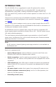
Introduction The AP-4000MR-LR is a ruggedized tri-mode AP optimized for outdoor deployments. It is equipped with one embedded 802.11a radio and one embedded 802.11b/g radio, enabling simultaneous support of 802.11a, 802.11b, and 802.11g clients as well as Mesh operation on either the 2.4 or 5.8 GHz band. There are two versions of the AP-4000MR-LR hardware. Differences between hardware versions are highlighted in this manual as necessary. See Figure 1 and Figure 2.
Figure 1: AP-4000MR-LR Unit (Dual LEDs and Serial Connection) Figure 2: AP-4000MR-LR R1 Unit (Single LED and No Serial Connection) Page Copyright © 2006 Proxim Wireless
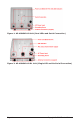
Authorized Antennas This product does not contain internal antennas. At least one external antenna must be used to make the product operational. For the 2.4 and 5.8 GHz bands, the following antennas are authorized: Antenna Type Max Antenna Gain Authorized (2.4 GHz) Max Antenna Gain Authorized (5.
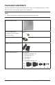
Package Contents Each AP-4000MR-LR shipment includes the items in the following table. Verify that you have received all parts of the shipment. Note: Unless listed here, cables are not included with the unit. AP-4000MR-LR Unit RJ11 to DB9 serial connector (not included with R1 units) Installation CD Power Injector and Cord (1) Cable Termination Kit Kit includes:. A. RJ45 connectors (2). B. Sealing caps (2). C. Sealing nut. D. Lock nut. E.
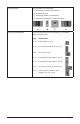
Mounting Kit Kit includes the following:. A. Mounting clamp for wall/pole. B. Extension arm. C. Mounting plate to enclosure. D. Mounting clamp for pole mounting A Mounting Hardware All rights reserved B C D The following mounting hardware is included with mounting kit: Qty. Description 6 ea Plain washer #5/16 2 ea. Hex cap screw NC 5/16-18 x 35 2 ea. Nut NC 5/16-18 4 ea. Helical spring lock washer # 1/4 4 ea.
Hardware and Software Installation IMPORTANT! Before installing this product, see Safety and Regulatory Compliance Information on the product CD for important information. IMPORTANT! All AP-4000MR-LR units must be installed by a suitably trained professional installation technician or by a qualified installation service.
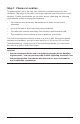
Step 1: Choose a Location To make optimal use of the unit, you must find a suitable location for the hardware. The range of the radio unit largely depends upon the position of the antenna. Proxim recommends you do a site survey, observing the following requirements, before mounting the hardware. ▪ The location must allow easy disconnection of power to the radio if necessary. ▪ Air must be able to flow freely around the hardware. ▪ The radio unit must be kept away from vibration and excessive heat.
Step 2: Pre-Assemble the Hardware 1. Unpack the unit and accessories from the shipping box. 2. Note the Ethernet and MAC addresses of the unit, as well as the serial number; these addresses may be used when configuring the unit. Note: The serial number is required to obtain support from Proxim. Keep this information in a safe place. 3. You will be attaching an outdoor-rated 24 AWG CAT5 cable (diameter .114 to .250 inches/2.9 to 6.
Caution! The sealing nut (A) must not be tightened until the sealing cap (C) over the RJ45 connector has been tightened to the unit during final installation; otherwise, the Ethernet cable may twist and become damaged. Notes: ▪ The cable must feed through all parts of the weatherproof cap before the RJ45 is crimped on the outdoor Ethernet a cable. ▪ The cable between the power injector and the unit must be a straightthrough Ethernet cable (without crossover).
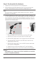
6. Attach the mounting bracket (C) to extension arm (B) with the screw, nut, and washers provided. 7. Tighten assembly (Torque 15 N∙m/130 in-lbs).
Step 3: Connect the Cables 1. If you have not already done so, connect the normal RJ45 connector on an outdoor-rated CAT5 cable to the “Data and Power Out” port on the power injector. Note: On R1 versions, connect the cable to the port labeled “J1 Antenna” on the power injector (not pictured). This port has 48 VDC power on the RJ45. 2. Attach the other end of the CAT5 cable with RJ45 connector to the Power and Ethernet port on the back of the unit (see the following figure).
3. To connect the unit through a hub or a switch to a PC, use a straightthrough Ethernet cable between the network interface card in the PC and the hub, and between the hub and the RJ45 “Data In” port on the PoE adapter. Note: On R1 units, connect the cable between the hub and the RJ45 “J2 PC/ Router” port on the power injector (not pictured).
Step 4: Power on the Unit The power injector provides Power-over-Ethernet (PoE), supplying electricity and wired connectivity to the unit over a single 24 AWG CAT5 (diameter .114 to .250 inches/2.9 to 6.4 mm). The unit is not 802.3af-compatible. Always use the supplied power injector to ensure that the unit is powered properly. Note that the Active Ethernet module provides +48 VDC over a standard CAT5 Ethernet cable.
Step 5: View LEDs On most units, the LEDs are present at the unit’s Ethernet connector; unscrew the watertight cap if necessary to view the LEDs. NOTE: Make sure the domed sealing nut is loose before unscrewing the cap or the Ethernet cable may be twisted and damaged. When the unit is powered on, it performs startup diagnostics.
Step 6: Mount the Unit IMPORTANT! If the AP is going to be used as part of a Mesh network, you will need to perform initial configuration of the parameters mentioned in the Prerequisites section of this AP-4000MR-LR User Guide before you mount the AP. See the User Guide for more information on configuring these parameters. Caution: To ensure that water does not gather around the antenna connectors, mount the unit with the antenna connectors facing downward. 1.
Step 7: Complete Installation 1. Tighten the sealing nut (Torque 3 N∙m/25 in-lbs) and lock nut (Torque . 4 N∙m/35 in-lbs). CAUTION! Do not over-tighten! Over-tightening can cause the CAT5 cable to become pinched and can subsequently damage the power injector or the unit. 2. Tighten the RJ45 sealing cap. CAUTION! Be sure you have re-installed the waterproof caps on the serial and Ethernet port connections.
Step 8: Install Documentation and Software To install the documentation and software on a computer or network: 1. Place the CD in a CD-ROM drive. The installer normally starts automatically. (If the installation program does not start automatically, click setup.exe on the installation CD.) 2. Follow the instructions displayed on the installer windows.
Unit Initialization Using ScanTool ScanTool is a software utility that is included on the installation CD-ROM. It is an initial configuration tool that allows you to find the IP address of an Access Point by referencing the MAC address in a Scan List, or to assign an IP address if one has not been assigned. The tool automatically detects the Access Points installed on your network, regardless of IP address, and lets you configure each unit’s IP settings.
Note: If your Access Point does not appear in the Scan List, click the Rescan button to update the display. If the unit still does not appear in the list, see the Troubleshooting chapter in the AP-4000MR-LR User Guide for suggestions. Note that after rebooting an Access Point, it may take up to five minutes for the unit to appear in the Scan List. 3.
d. Enter a static IP Address for the AP in the field provided. You must assign the unit a unique address that is valid on your IP subnet. e. Enter your network’s Subnet Mask. f. Enter your network’s Gateway IP Address. g. Enter the SNMP read/write password in the Read/Write Password field. For new units, the default password is public. h. Click OK to save your changes. The Access Point will reboot automatically and any changes you made will take effect. i.
5. Enter the HTTP password in the Password field. Leave the User Name field blank. For new units, the default HTTP password is public. If you are logging on for the first time the Setup Wizard will launch automatically. Note Setup Wizard will not relaunch on subsequent logins. To force the Setup Wizard to launch upon login, click htManagement > Services and choose Enable from the Setup Wizard drop down menu. 6. To configure the AP using the Setup Wizard, see Using the Setup Wizard, below.
configuration screen. Note that clicking a link in the navigation panel will not submit any changes you made to the unit’s configuration on the current page. ▪ Exit: To exit from the Setup Wizard at any time, click Step 1: Introduction on the navigation panel, and then click the Exit button. CAUTION: If you exit from the Setup Wizard, any changes you submitted (by clicking the Save & Next button) up to that point will be saved to the unit but will not take effect until it is rebooted. 2.
2. Click Commands > Update AP > via HTTP. The Update AP via HTTP screen will be displayed. 3. From the File Type drop-down menu, select Image. 4. Use the Browse button to locate or manually type in the name of the file (including the file extension) you downloaded from the Proxim Knowledgebase. If typing the file name, you must include the full path and the file extension in the file name text box. 5. To initiate the HTTP Update operation, click the Update AP button.
FREQUENCIES AND BANDWIDTHS 2.4 GHz Frequencies and Bandwidths Channel Center Frequency (MHz) 20 MHz 1 2412 2 2417 3 2422 4 2427 5 2432 6 2437 7 2442 8 2447 9 2452 10 2457 11 2462 = Occupied bandwidth for specified center frequency. 5.8 GHz Frequencies and Bandwidths Channel Center Frequency (MHz) 20 MHz 149 5745 153 5765 157 5785 161 5805 165 5825 = Occupied bandwidth for specified center frequency.
Technical services and support If you are having trouble utilizing your Proxim product, please review the AP4000MR-LR User Guide and the additional documentation provided with your product. If you require additional support, please refer to the “Technical Services and Support” chapter in the AP-4000MR-LR User Guide for details about the information you will need to gather before using the Support Options listed below.
www.proxim.