ORiNOCO AP-4000, AP-4000M and AP-4900M User Guide
AP-4000/4000M/4900M User Guide IMPORTANT! Before installing and using this product, see the Safety and Regulatory Compliance Guide located on the product CD. Copyright © 2007 Proxim Wireless Corporation. All rights reserved. Covered by one or more of the following U.S. patents: 5,231,634; 5,875,179; 6,006,090; 5,809,060; 6,075,812; 5,077,753. This User Guide and the software described in it are copyrighted with all rights reserved.
AP-4000/4000M/4900M User Guide Contents 1 Introduction . . . . . . . . . . . . . . . . . . . . . . . . . . . . . . . . . . . . . . . . . . . . . . . . . . . . . . . . . . . . . . . . . . 8 Products Covered in this User Guide . . . . . . . . . . . . . . . . . . . . . . . . . . . . . . . . . . . . . . . . . . . . . . . . . . . . . . 8 Introduction to Wireless Networking . . . . . . . . . . . . . . . . . . . . . . . . . . . . . . . . . . . . . . . . . . . . . . . . . . . . . . . 8 Mesh Networking . . . . . .
AP-4000/4000M/4900M User Guide Dynamic DNS Support . . . . . . . . . . . . . . . . . . . . . . . . . . . . . . . . . . . . . . . . . . . . . . . . . . . . . . . . . . . . . . . . . . . . . . 45 Network . . . . . . . . . . . . . . . . . . . . . . . . . . . . . . . . . . . . . . . . . . . . . . . . . . . . . . . . . . . . . . . . . . . . . . . . . . . 46 IP Configuration . . . . . . . . . . . . . . . . . . . . . . . . . . . . . . . . . . . . . . . . . . . . . . . . . . . . . . . . . . . . . . . . . . . . . .
AP-4000/4000M/4900M User Guide RADIUS Accounting. . . . . . . . . . . . . . . . . . . . . . . . . . . . . . . . . . . . . . . . . . . . . . . . . . . . . . . . . . . . . . . . . . . . . . . .119 SSID/VLAN/Security . . . . . . . . . . . . . . . . . . . . . . . . . . . . . . . . . . . . . . . . . . . . . . . . . . . . . . . . . . . . . . . . 121 VLAN Overview . . . . . . . . . . . . . . . . . . . . . . . . . . . . . . . . . . . . . . . . . . . . . . . . . . . . . . . . . . . . . . . . . . . . . . . . . .
AP-4000/4000M/4900M User Guide Client Connection Problems. . . . . . . . . . . . . . . . . . . . . . . . . . . . . . . . . . . . . . . . . . . . . . . . . . . . . . . . . . . . . . . . . 165 VLAN Operation Issues . . . . . . . . . . . . . . . . . . . . . . . . . . . . . . . . . . . . . . . . . . . . . . . . . . . . . . . . . . . . . . . . . . . . 165 Power-Over-Ethernet (PoE) . . . . . . . . . . . . . . . . . . . . . . . . . . . . . . . . . . . . . . . . . . . . . . . . . . . . . . . . . . . . . . . . .
AP-4000/4000M/4900M User Guide Security Parameters. . . . . . . . . . . . . . . . . . . . . . . . . . . . . . . . . . . . . . . . . . . . . . . . . . . . . . . . . . . . . . . . . . . . . . . 233 VLAN/SSID Parameters. . . . . . . . . . . . . . . . . . . . . . . . . . . . . . . . . . . . . . . . . . . . . . . . . . . . . . . . . . . . . . . . . . . . 235 Other Parameters. . . . . . . . . . . . . . . . . . . . . . . . . . . . . . . . . . . . . . . . . . . . . . . . . . . . . . . . . . . . . . . . . . . . . .
AP-4000/4000M/4900M User Guide 1 Introduction This chapter contains information on the following: • Products Covered in this User Guide • Introduction to Wireless Networking • Mesh Networking • Guidelines for Roaming • Management and Monitoring Capabilities Products Covered in this User Guide This User Guide details functionality of the following products: Product AP-4000 AP-4000M AP-49000M Description Tri-mode AP that supports: • 802.11b, 802.11g, and 802.
Introduction Introduction to Wireless Networking AP-4000/4000M/4900M User Guide Figure 1-1 Typical Wireless Network Access Infrastructure 9
Introduction Mesh Networking AP-4000/4000M/4900M User Guide Mesh Networking Using the ORiNOCO Mesh Creation Protocol (OMCP), the AP-4000/4000M/4900M supports structured Mesh networking. In a Mesh network, access points use their wireless interface as a backhaul to the rest of the network.
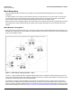
Introduction Mesh Networking AP-4000/4000M/4900M User Guide are discovered, MAP2 through MAP8 will build a neighbor table from the beacons and probe responses they receive. The neighbor table contains three kinds of links: • Active: Link with a Mesh neighbor that has gone through association and authentication, and the port is open. • Connected: Link with a Mesh neighbor that has gone through association and authentication, but the port is closed.
Introduction Mesh Networking AP-4000/4000M/4900M User Guide After a short while, the network in this example will look like Figure 1-4, where solid lines indicate active Mesh links and dotted lines indicate established but inactive Mesh links. Figure 1-4 Mesh Startup Topology Example – Step 3 In this example, if MAP8 loses the Mesh link to MP9, MAP8 will immediately activate the Mesh link to MAP7.
Introduction Guidelines for Roaming – AP-4000/4000M/4900M User Guide Average utilization (time that a client is actually transferring data) is 10%. If the conditions on your network are different than the assumptions above, then the maximum number of APs should be adjusted accordingly. NOTE: Clients whose traffic must traverse multiple hops in order to reach the portal will have lower throughput than clients whose traffic traverses fewer hops.
Introduction Management and Monitoring Capabilities • HTTP/HTTPS Interface • Command Line Interface • SNMP Management • SSH (Secure Shell) Management AP-4000/4000M/4900M User Guide HTTP/HTTPS Interface The HTTP Interface (Web browser Interface) provides easy access to configuration settings and network statistics from any computer on the network. You can access the HTTP Interface over your LAN (switch, hub, etc.
Introduction Management and Monitoring Capabilities AP-4000/4000M/4900M User Guide Enterprise MIB for more information; the MIB can be opened with any text editor, such as Microsoft Word, Notepad, or WordPad. SNMPv3 Secure Management SNMPv3 is based on the existing SNMP framework, but addresses security requirements for device and network management.
AP-4000/4000M/4900M User Guide Installation and Initialization 2 In this chapter: • • AP-4000/4000M/4900M Hardware Description – Overview – LED Indicators – Power-over-Ethernet (PoE) – Antennas Prerequisites – General Prerequisites – Mesh Prerequisites • System Requirements • Product Package • Hardware Installation • – Attach Cables – Install the Security Cover (Optional) – Mount the AP-4000/4000M/4900M – Power On the Unit – Install External Antennas (Professional Installati
Installation and Initialization AP-4000/4000M/4900M Hardware Description AP-4000/4000M/4900M User Guide AP-4000/4000M/4900M Hardware Description Overview The AP-4000 and AP-4000M are tri-mode APs equipped with the following embedded radios: • One embedded 802.11a radio and one embedded 802.11b/g radio, enabling simultaneous support of 802.11a, 802.11b, and 802.11g clients as well as Mesh operation on either the 2.4 or 5 GHz band.
Installation and Initialization AP-4000/4000M/4900M Hardware Description Ethernet Wireless Interfaces AP-4000/4000M/4900M User Guide Power Figure 2-2 LED Indicators on the Top Panel Power-over-Ethernet (PoE) The AP-4000/4000M/4900M is equipped with an 802.3af-compliant Power-over-Ethernet (PoE) module. PoE delivers both data and power to the access point over a single Ethernet cable. If you choose to use PoE, there is no difference in operation; the only difference is in the power source.
Installation and Initialization AP-4000/4000M/4900M Hardware Description AP-4000/4000M/4900M User Guide External Antennas The AP-4000/4000M/4900M also has four antenna connectors, two on each radio, for use with external antennas.External antennas can be used with either radio on the AP-4000/4000M/4900M. NOTE: All AP-4900M units, and AP-4000/4000M units using external antennas, must be installed by a suitably trained professional installation technician or by a qualified installation service.
Installation and Initialization AP-4000/4000M/4900M Hardware Description AP-4000/4000M/4900M User Guide 4.9 GHz Antenna On the AP-4900M, antenna connector 3 is equipped with a pigtail adaptor for connection to a 4.9 GHz antenna. When the AP-4900M is configured to operate in the 4.9 GHz Public Safety operational mode, antenna diversity is automatically disabled by default, and antenna 3 is configured for use. Connecting an external antenna to this antenna port disables the corresponding internal antenna.
Installation and Initialization Prerequisites AP-4000/4000M/4900M User Guide Prerequisites General Prerequisites Before installing your unit, you need to gather certain network information. The following table identifies the information you need. Network Name (SSID of the wireless cards) You must assign the Access Point a Network Name before wireless users can communicate with it. The clients also need the same Network Name. This is not the same as the System Name, which applies only to the Access Point.
Installation and Initialization System Requirements AP-4000/4000M/4900M User Guide Mesh Prerequisites Before setting up a Mesh network, gather the following information: Mesh Mode The mode in which the AP will be used. If the AP will be connected directly to the wired backbone, it should be configured for Mesh Portal mode; if it will connect to the Portal and backbone wirelessly, it should be configured for Mesh AP mode. If the AP will not be used in a Mesh network, Mesh Mode can be disabled.
Installation and Initialization Product Package AP-4000/4000M/4900M User Guide Product Package Each AP-4000/4000M/4900M shipment includes the items in the following table. Verify that you have received all parts of the shipment. NOTE: Unless noted in this table, cables are not supplied with the unit.
Installation and Initialization Hardware Installation AP-4000/4000M/4900M User Guide Hardware Installation NOTE: All AP-4900M units, and AP-4000/4000M units using external antennas, must be installed by a suitably trained professional installation technician or by a qualified installation service. NOTE: Before installing and using this product, see the Safety and Regulatory Compliance Guide. NOTE: Avant d’installer et d’utiliser ce produit, consultez le manuel Safety and Regulatory Compliance Guide.
Installation and Initialization Hardware Installation • AP-4000/4000M/4900M User Guide Use a cross-over Ethernet cable or adapter if you intend to connect the unit to a single computer. Figure 2-4 Cabling without PoE 3. Optionally, connect an RS-232 cable (not shown) to the RS-232 console port (the right port, labeled “RS-232”). NOTE: You cannot install the security cover to the AP-4000/4000M/4900M if an RS-232 cable is connected. 4. Continue with Install the Security Cover (Optional).
Installation and Initialization Hardware Installation AP-4000/4000M/4900M User Guide Install the Security Cover (Optional) You can optionally install a security cover to deter unauthorized access to the unit. The security cover is a plastic enclosure that prevents access to the cabling and the Reset and Reload buttons. 1.
Installation and Initialization Hardware Installation AP-4000/4000M/4900M User Guide Wall Mounting Follow these steps to mount the unit on a wall: 1. If the unit’s power supply is plugged in, unplug it. 2. Put the mounting plate up to the wall so that the embossed letter “L” is on top (see figure). If the plate is correctly oriented, the circular tab that is vertically aligned with the square hole should be on top. 3. Fasten the mounting plate with two screws through the circular holes of the plate.
Installation and Initialization Hardware Installation AP-4000/4000M/4900M User Guide 2. Screw through the mounting plate. 3. Place the AP up against the mounting plate. Orient the AP with the long access vertical, with the connectors facing right. Power On the Unit The AP can be powered by a power supply (just plug the power cord of the power supply into an AC power outlet), or by Power-over-Ethernet (connect a PoE DC injector to the Ethernet cable).
Installation and Initialization Hardware Installation AP-4000/4000M/4900M User Guide NOTE: AP-4000 models 8670-US2 and 8670-AU do not provide external antenna connectors for 5 GHz (802.11a) operation. Figure 2-8 Opening the Antenna Compartment 2. There are four antenna connectors in the AP-4000/4000M/4900M, labeled 1 through 4. Connectors 1 and 2 are for the 802.11b/g radio, and connectors 3 and 4 and for the 802.11a/4.9 GHz radio.
Installation and Initialization Hardware Installation AP-4000/4000M/4900M User Guide Connecting Antenna(s) to the AP-4900M for 4.9 GHz Operation To attach an external antenna to the AP-4900M, attach the selected antenna to the pigtail attachment connected to the AP’s antenna connector 3 (see Figure 2-10). For a list of recommended antennas, see http://www.proxim.com/products/wifi/accessories.
Installation and Initialization Hardware Installation AP-4000/4000M/4900M User Guide Antenna Types and Maximum Gain For devices using external antennas, professional installers should select only the antenna types listed in the following table, with gain not exceeding the listed maximum gain for each type. Frequency Band 2.4 GHz 5 GHz 4.9 GHZ Antenna Type Omni Panel Yagi Parabolic Omni Panel Sector Parabolic No restriction Maximum Gain 10 14 14 24 13 28.2 17 33.4 No restriction beyond EIRP compliance.
Installation and Initialization Initialization AP-4000/4000M/4900M User Guide Initialization The following sections detail how to initialize the AP using ScanTool, log in to the HTTP interface, perform an initial configuration of the AP using the Setup Wizard, and download the required AP software. • Using ScanTool • Logging In • Using the Setup Wizard • Installing the Software Using ScanTool ScanTool is a software utility that is included on the installation CD-ROM.
Installation and Initialization Initialization AP-4000/4000M/4900M User Guide NOTE: If your Access Point does not appear in the Scan List, click the Rescan button to update the display. If the unit still does not appear in the list, see Troubleshooting for suggestions. Note that after rebooting an Access Point, it may take up to five minutes for the unit to appear in the Scan List. 4. Do one of the following: • If the AP has been assigned an IP address by a DHCP server on the network: a.
Installation and Initialization Initialization AP-4000/4000M/4900M User Guide k. Click the Change button to return to the Change screen. l. Click the Web Configuration button at the bottom of the Change screen. m. Proceed to the Logging In section for information on how to access the HTTP interface using this IP address. Logging In Once the AP has a valid IP Address and an Ethernet connection, you may use your web browser to monitor and configure the AP.
Installation and Initialization Initialization AP-4000/4000M/4900M User Guide Figure 2-14 System Status Screen The buttons on the left of the screen provide access to the monitoring and configuration options for the AP. See Advanced Configuration to begin configuring the AP manually. You can also exit the Web interface or reboot the AP using these buttons. The Command Line Interface (CLI) also provides a method for monitoring and configuring the AP using Telnet or a serial connection.
Installation and Initialization Initialization AP-4000/4000M/4900M User Guide • Save & Next Button: Each Setup Wizard screen has a Save & Next button. Click this button to submit any changes you made to the unit’s parameters and continue to the next page. The instructions below describe how to navigate the Setup Wizard using the Save & Next buttons. • Navigation Panel: The Setup Wizard provides a navigation panel on the left-hand side of the screen.
Installation and Initialization Initialization AP-4000/4000M/4900M User Guide — Primary Network Name (SSID): Enter a Network Name (between 1 and 32 characters long) for the wireless network. You must configure each wireless client to use this name as well. Note that the unit supports up to 16 SSIDs/VLANs per wireless interface. Please see the Advanced Configuration chapter for information on the detailed rules on configuring multiple SSIDs, VLANs, and security profiles.
Installation and Initialization Initialization AP-4000/4000M/4900M User Guide 2. If prompted, create an account to gain access. NOTE: The Knowledgebase is available to all website visitors. First-time users will be asked to create an account to gain access. 3. Click Search Knowledgebase. 4. In the Search Knowledgebase field, enter one of the following: • For the AP-4000: 1250. • For the AP-4000M: 1934. • For the AP-4900M: 1851. 5. Click Search. 6.
Installation and Initialization Initialization AP-4000/4000M/4900M User Guide Figure 2-17 Warning Message 5. Click OK to continue with the operation or Cancel to abort the operation. 6. If the operation is unsuccessful, you will receive an error message. If this occurs, see the Troubleshooting chapter or attempt installing the software with a TFTP server, as described in the next section. If the operation is successful, you will receive a confirmation message. 7.
Installation and Initialization Initialization AP-4000/4000M/4900M User Guide 4. Enter the IP address of your TFTP server in the field provided. 5. Enter the File Name (including the file extension). If the file is located in the default TFTP directory, you need enter only the file name. Otherwise, enter the full directory path and file name. 6. Select the File Type from the drop-down menu (use Img for software updates). 7. Select Download & Reboot from the File Operation drop-down menu. 8. Click OK.
AP-4000/4000M/4900M User Guide System Status 3 The first screen displayed after Logging In is the System Status screen. You can always return to this screen by clicking the Status button. Figure 3-1 System Status Screen The System Status screen provides the following information: • System Status: This area provides system-level information, including the unit’s IP address and contact information. See System for information on these settings. • System Alarms: System traps (if any) appear in this area.
AP-4000/4000M/4900M User Guide Advanced Configuration 4 This chapter contains information on configuring settings in the following categories: • System: Configure specific system information such as system name and contact information. • Network: Configure IP, DNS client, DHCP server, DHCP Relay Agent, DHCP Relay Servers, Link Integrity, and SNTP settings. • Interfaces: Configure the Access Point’s interfaces: Wireless A, Wireless B, Ethernet, and Mesh.
Advanced Configuration AP-4000/4000M/4900M User Guide Figure 4-1 Configure Main Screen 2. Click the tab that corresponds to the parameter you want to configure. For example, click Network to configure the Access Point’s TCP/IP settings. Each Configure tab is described in the remainder of this chapter.
Advanced Configuration System AP-4000/4000M/4900M User Guide System You can configure and view the following parameters within the System Configuration screen: • Name: The name assigned to the AP. See the Dynamic DNS Support and Access Point System Naming Convention sections for rules on naming the AP. • Country: The country in which the AP will be used. Note that some countries have two selectable options (one for indoor use and one for outdoor use).
Advanced Configuration System AP-4000/4000M/4900M User Guide Figure 4-2 System Tab Dynamic DNS Support DNS is a distributed database mapping the user readable names and IP addresses (and more) of every registered system on the Internet. Dynamic DNS is a lightweight mechanism which allows for modification of the DNS data of host systems whose IP addresses change dynamically.
Advanced Configuration Network AP-4000/4000M/4900M User Guide Network The Network tab contains the following sub-tabs: • IP Configuration • DHCP Server • DHCP Relay Agent • Link Integrity • SNTP (Simple Network Time Protocol) IP Configuration This tab is used to configure the internet (TCP/IP) settings for the access point. These settings can be either entered manually (static IP address, subnet mask, and gateway IP address) or obtained automatically (dynamic).
Advanced Configuration Network AP-4000/4000M/4900M User Guide Basic IP Parameters • IP Address Assignment Type: Set this parameter to Dynamic to configure the Access Point as a Dynamic Host Configuration Protocol (DHCP) client; the Access Point will obtain IP settings from a network DHCP server automatically during boot-up. If you do not have a DHCP server or if you want to manually configure the Access Point’s IP settings, set this parameter to Static.
Advanced Configuration Network AP-4000/4000M/4900M User Guide Figure 4-4 DHCP Server Configuration Screen You can configure and view the following parameters within the DHCP Server Configuration screen: NOTE: You must reboot the AP before changes to any of these DHCP server parameters take effect. • Enable DHCP Server: Place a check mark in the box provided to enable DHCP Server functionality.
Advanced Configuration Network AP-4000/4000M/4900M User Guide NOTE: The Default Lease Time cannot be larger than the Maximum Lease Time. If you set the Maximum Lease Time, you should also set the Default Lease Time to ensure that the Default Lease Time is less than the Maximum. – Comment (optional) – Status: IP Pools are enabled upon entry in the table. You can also disable or delete entries by changing this field’s value.
Advanced Configuration Network AP-4000/4000M/4900M User Guide DHCP Server IP Address Table The AP supports the configuration of a maximum of 10 server settings in the DHCP Relay Agents server table. At least one server must be configured to enable DHCP Relay. To add entries to the table of DHCP Relay Agents, click Add in the DHCP Server IP Address Table; to edit existing entries, click Edit. The following window is displayed.
Advanced Configuration Network AP-4000/4000M/4900M User Guide Figure 4-7 Link Integrity Configuration Screen SNTP (Simple Network Time Protocol) SNTP allows a network entity to communicate with time servers in the network/internet to retrieve and synchronize time of day information. When this feature is enabled, the AP will attempt to retrieve the time of day information from the configured time servers (primary or secondary), and, if successful, will update the relevant time objects in the AP.
Advanced Configuration Network AP-4000/4000M/4900M User Guide Figure 4-8 SNTP Configuration Screen You can configure and view the following parameters within the SNTP screen: • SNTP Status: Select Enable or Disable from the drop-down menu. The selected status will determine which of the parameters on the SNTP screen are configurable. NOTE: When SNTP is enabled, it will take some time for the AP to retrieve the time of day from the configured time servers and update the relevant date and time parameters.
Advanced Configuration Network – Year: Enter the current year. – Month: Enter the month in digits (1-12). – Day: Enter the day in digits (1-31). – Hour: Enter the hour in digits (0-23). – Minutes: Enter the minutes in digits (0-59). – Seconds: Enter the seconds in digits (0-59).
Advanced Configuration Interfaces AP-4000/4000M/4900M User Guide Interfaces From the Interfaces tab, you configure the Access Point’s operational mode settings, power control settings, wireless interface settings and Ethernet settings. You may also configure a Wireless Distribution System for AP-to-AP communications. The Interfaces tab contains the following sub-tabs: • Operational Mode • Wireless-A (802.11a/4.9 GHz Radio) and Wireless-B (802.
Advanced Configuration Interfaces AP-4000/4000M/4900M User Guide Figure 4-10 Operational Mode Screen (AP-4900M) The Wireless-A interface operates in 802.11a mode on the AP-4000/4000M and in either 802.11a mode or 4.9 GHz Public Safety mode on the AP-4900M. In 4.9 GHz Public Safety mode, you must also select a Channel Bandwidth. This option is not configurable in the AP-4000/4000M. See Available Channels for a list of channels available with each bandwidth.
Advanced Configuration Interfaces AP-4000/4000M/4900M User Guide Enable H Band Support In compliance with FCC regulations, Dynamic Frequency Selection is required in the middle frequency band (M band: 5.25 GHz - 5.25 Ghz) and high frequency band (H band: 5.470 GHz - 5.725 GHz). DFS is enabled automatically when you use one or both of these frequency bands.
Advanced Configuration Interfaces AP-4000/4000M/4900M User Guide The same information is transmitted in probe response frames in response to a client’s probe requests. Once the client has acquired the information required to meet the transmit requirements of the regulatory domain, it configures itself for operation in the regulatory domain. On some AP models, the regulatory domain and associated parameters are automatically configured when a country is selected on the System tab.
Advanced Configuration Interfaces AP-4000/4000M/4900M User Guide 4. Click OK.
Advanced Configuration Interfaces AP-4000/4000M/4900M User Guide Wireless-A (802.11a/4.9 GHz Radio) and Wireless-B (802.
Advanced Configuration Interfaces AP-4000/4000M/4900M User Guide You can view and configure the following parameters for the Wireless-A and Wireless-B interfaces: NOTE: You must reboot the Access Point before any changes to these parameters take effect. • Physical Interface Type: For Wireless Interface A on the AP-4000/4000M, this field reports “802.11a (OFDM 5 GHz).” On the AP-4900M, this field reports “802.11a (OFDM 5 GHz)” when operating in 802.11a mode, and “Public Safety (OFDM 4.
Advanced Configuration Interfaces AP-4000/4000M/4900M User Guide – For 802.11b/g -- Auto Fallback, 1, 2, 5.5, 6, 9, 11, 12, 18, 24, 36, 48, 54 Mbits/sec – For 802.11g-wifi -- Auto Fallback, 1, 2, 5.5, 6, 9, 11, 12, 18, 24, 36, 48, 54 Mbits/sec NOTE: 802.11g-wifi has been defined for Wi-Fi testing purposes. It is not recommended for use in your wireless network environment. NOTE: Turbo mode is supported in only in 802.11a mode in the FCC regulatory domain when DFS is not required.
Advanced Configuration Interfaces • 48: 5.240 GHz • 149: 5.745 GHz • 153: 5.765 GHz • 157: 5.785 GHz • 161: 5.805 GHz • 165: 5.825 GHz AP-4000/4000M/4900M User Guide If you are using the unit in a country and band that require DFS, keep in mind the following: • DFS is not a configurable parameter; it is always enabled and cannot be disabled. • You cannot manually select the device’s operating channel; you must let the unit select the channel.
Advanced Configuration Interfaces AP-4000/4000M/4900M User Guide RTS/CTS Medium Reservation The 802.11 standard supports optional RTS/CTS communication based on packet size. Without RTS/CTS, a sending radio listens to see if another radio is already using the medium before transmitting a data packet. If the medium is free, the sending radio transmits its packet. However, there is no guarantee that another radio is not transmitting a packet at the same time, causing a collision.
Advanced Configuration Interfaces AP-4000/4000M/4900M User Guide When the wireless service is resumed on a wireless interface, the AP generate a trap called oriTrapWirelessServiceResumed. Channel Blacklist Table The Channel Blacklist table contains all available channels (channels vary based on regulatory domain). It can be used to manually blacklist channels, and it also reflects channels that have been automatically blacklisted by the Dynamic Frequency Selection/Radar Detection (DFS/RD) function.
Advanced Configuration Interfaces AP-4000/4000M/4900M User Guide Figure 4-13 Channel Blacklist Table - Edit Screen NOTE: Wireless service can be shut down/resumed on each wireless interface individually. Wireless Distribution System (WDS) A Wireless Distribution System (WDS) creates a link between two 4.9 GHz, 802.11a, 802.11b, or 802.11b/g APs over their radio interfaces. This link relays traffic from one AP that does not have Ethernet connectivity to a second AP that has Ethernet connectivity.
Advanced Configuration Interfaces AP-4000/4000M/4900M User Guide Bridging WDS Each WDS link is mapped to a logical WDS port on the AP. WDS ports behave like Ethernet ports rather than like standard wireless interfaces: on a BSS port, an Access Point learns by association and from frames; on a WDS or Ethernet port, an Access Point learns from frames only.
Advanced Configuration Interfaces AP-4000/4000M/4900M User Guide Figure 4-15 WDS Configuration 5. Click the Edit button to update the Wireless Distribution System (WDS) Table.
Advanced Configuration Interfaces AP-4000/4000M/4900M User Guide 6. Select which encryption method to use (if any) from the WDS Security Mode drop-down menu. 7. If you selected a WDS Security Mode, do one of the following: • If you selected WEP: Enter an encryption key. • If you selected AES: Enter a shared secret. 8. Enter the MAC Address that you wrote down in Step 2 in one of the Partner MAC Address field of the Wireless Distribution Setup window. 9. Set the Status of the device to Enable. 10.
Advanced Configuration Interfaces AP-4000/4000M/4900M User Guide Mesh Mesh functionality can be enabled on only one of the AP’s wireless interfaces. When configured for Mesh, the AP’s wireless interface simultaneously functions as a Mesh link and as a radio to service clients. CAUTION: Mesh mis-configuration may cause problems in your wireless network. Before configuring an interface for Mesh functionality, see Mesh Network Configuration. NOTE: AP-4000 units must use software version 3.
Advanced Configuration Interfaces AP-4000/4000M/4900M User Guide • Mesh Radio: Select the wireless interface on which to enable Mesh functionality. Select Wireless Interlace A (802.11a/4.9 GHz radio) or Wireless Interface B (802.11b/g radio). • Mesh SSID: Enter a unique Mesh Network Name (SSID) between 1 and 16 characters. NOTE: Do not use quotation marks (single or double) in the Network Name; this will cause the AP to misinterpret the name.
Advanced Configuration Interfaces AP-4000/4000M/4900M User Guide Click on the Advanced button on the Interfaces > Mesh page to access advanced Mesh parameters. The parameters on the Advanced Mesh Parameters page are preconfigured with default settings that optimize the type of network identified in the Mesh Mobility parameter on the previous page. Proxim recommends changing these values only if you have advanced knowledge of Mesh networking.
Advanced Configuration Interfaces AP-4000/4000M/4900M User Guide NOTE: When enabling Auto Switch Mode, Proxim recommends that you also enable Auto Channel Select. ACS is configured on the Wireless A or Wireless B page. See Wireless-A (802.11a/4.9 GHz Radio) and Wireless-B (802.11b/g Radio) for more information. • Current Mesh Mode: Displays the current Mesh mode of the AP (Mesh Portal or Mesh AP).
Advanced Configuration Management AP-4000/4000M/4900M User Guide Management The Management tab contains the following sub-tabs: • Passwords • IP Access Table • Services • Automatic Configuration (AutoConfig) • Hardware Configuration Reset (CHRD) Passwords Passwords are stored in flash memory and secured using encryption. You can configure the following passwords: • SNMP Read Community Password: The password for read access to the AP using SNMP.
Advanced Configuration Management AP-4000/4000M/4900M User Guide IP Access Table The Management IP Access table limits in-band management access to the IP addresses or range of IP addresses specified in the table. This feature applies to all management services (SNMP, HTTP, and CLI) except for CLI management over the serial port. To configure this table, click Add and set the following parameters: • IP Address: Enter the IP Address for the management station.
Advanced Configuration Management • AP-4000/4000M/4900M User Guide Secure Management Status: Enables the further configuration of HTTPS Access, SNMPv3, and Secure Shell (SSH). After enabling Secure Management, you can choose to configure HTTPS (SSL) and Secure Shell access on the Services tab, and to configure SNMPv3 passwords on the Passwords tab.
Advanced Configuration Management AP-4000/4000M/4900M User Guide Figure 4-20 Management Services Configuration Screen 76
Advanced Configuration Management AP-4000/4000M/4900M User Guide Telnet Configuration Settings • Telnet Interface Bitmask: Select the interface (Ethernet, Wireless-Slot A, Wireless-Slot B, All Interfaces) from which you can manage the AP via telnet. This parameter can also be used to Disable telnet management. • Telnet Port Number: The default port number for Telnet applications is 23.
Advanced Configuration Management AP-4000/4000M/4900M User Guide NOTE: When Secure Management is enabled on the AP, SSH will be enabled by default and cannot be disabled. Host keys must either be generated externally and uploaded to the AP (see Uploading Externally Generated Host Keys), generated manually, or auto-generated at the time of SSH initialization if SSH is enabled and no host keys are present. There is no key present in an AP that is in a factory default state.
Advanced Configuration Management AP-4000/4000M/4900M User Guide Serial Configuration Settings The serial port interface on the AP is enabled at all times. See Setting IP Address using Serial Port for information on how to access the CLI interface via the serial port. You can configure and view the following parameters: • Serial Baud Rate: Select the serial port speed (bits per second). Choose between 2400, 4800, 9600, 19200, 38400, or 57600; the default Baud Rate is 9600.
Advanced Configuration Management AP-4000/4000M/4900M User Guide • RADIUS Profile for Management Access Control: Specifies the RADIUS Profile to be used for RADIUS Based Management Access. • Local User Status: Enables or disables the local user when RADIUS Based Management is enabled. The default local user ID is root. • Local User Password and Confirm Password: The default local user password is public.
Advanced Configuration Management AP-4000/4000M/4900M User Guide Figure 4-22 Automatic Configuration Screen Set up Automatic Configuration for Dynamic IP Perform the following procedure to enable and set up Automatic Configuration when you have a dynamic IP address for the TFTP server via DHCP. The Configuration filename and the TFTP server IP address are contained in the DHCP response when the AP gets its IP address dynamically from the DHCP server.
Advanced Configuration Management AP-4000/4000M/4900M User Guide Figure 4-23 DHCP Options: Setting the Boot Server Host Name 4. Add the Boot Server Hostname and Boot Filename parameters to the Available Options list. 5. Set the value of the Boot Server Hostname Parameter to the hostname or IP Address of the TFTP server. For example: 11.0.0.7. Figure 4-24 DHCP Options: Setting the Bootfile Name 6. Set the value of the Bootfile Name parameter to the Configuration filename. For example: AP-Config. 7.
Advanced Configuration Management AP-4000/4000M/4900M User Guide access to the AP is not protected, an unauthorized person could reset the AP to factory defaults and thus gain control of the AP. The user can disable the hardware configuration reset functionality to prevent unauthorized access.
Advanced Configuration Management AP-4000/4000M/4900M User Guide 2. Check (enable) or uncheck (disable) the Enable Hardware Configuration Reset checkbox. 3. Change the default Configuration Reset Password in the “Configuration Reset Password” and “Confirm” fields. 4. Click OK. 5. Reboot the AP. NOTE: It is important to safely store the configuration reset password.
Advanced Configuration Filtering AP-4000/4000M/4900M User Guide Filtering The Access Point’s Packet Filtering features help control the amount of traffic exchanged between the wired and wireless networks. There are four sub-tabs under the Filtering heading: • Ethernet Protocol • Static MAC • Advanced • TCP/UDP Port Ethernet Protocol The Ethernet Protocol Filter blocks or forwards packets based on the Ethernet protocols they support. Follow these steps to configure the Ethernet Protocol Filter: 1.
Advanced Configuration Filtering • AP-4000/4000M/4900M User Guide To add an entry, click Add, and then specify the Protocol Number and a Protocol Name. – Protocol Number: Enter the protocol number. See http://www.iana.org/assignments/ethernet-numbers for a list of protocol numbers. – Protocol Name: Enter related information, typically the protocol name.
Advanced Configuration Filtering AP-4000/4000M/4900M User Guide Figure 4-29 Static MAC Filter Configuration Each static MAC entry contains the following fields: • Wired MAC Address • Wired Mask • Wireless MAC Address • Wireless Mask • Comment: This field is optional. Each MAC Address or Mask is comprised of 12 hexadecimal digits (0-9, A-F) that correspond to a 48-bit identifier. (Each hexadecimal digit represents 4 bits (0 or 1).
Advanced Configuration Filtering AP-4000/4000M/4900M User Guide A maximum of 200 entries can be created in the Static MAC filter table. To create an entry, click Add and enter the appropriate MAC addresses and Masks to setup a filter. The entry is enabled automatically when saved. Figure 4-30 Static MAC Filter Table - Add Entries To edit an entry, click Edit. To disable or remove an entry, click Edit and change the Status field from Enable to Disable or Delete.
Advanced Configuration Filtering AP-4000/4000M/4900M User Guide Prevent All Wireless Devices from Communicating with a Single Wired Device Configure the following settings to prevent all three Wireless Clients from communicating with Wired Server 1: • Wired MAC Address: 00:40:F4:1C:DB:6A • Wired Mask: FF:FF:FF:FF:FF:FF • Wireless MAC Address: 00:00:00:00:00:00 • Wireless Mask: 00:00:00:00:00:00 Result: The Access Point blocks all traffic between Wired Server 1 and all wireless clients.
Advanced Configuration Filtering AP-4000/4000M/4900M User Guide Figure 4-31 Advanced Filter Configuration The following protocols are listed in the Advanced Filter Table: • Deny IPX RIP • Deny IPX SAP • Deny IPX LSP • Deny IP Broadcasts • Deny IP Multicasts The AP can filter these protocols in the wireless-to-Ethernet direction, the Ethernet-to-wireless direction, or in both directions. Click Edit and use the Status field to Enable or Disable the filter.
Advanced Configuration Filtering AP-4000/4000M/4900M User Guide Figure 4-32 Static MAC Filter Table - Edit Entries TCP/UDP Port Port-based filtering enables you to control wireless user access to network services by selectively blocking TCP/UDP protocols through the AP.
Advanced Configuration Filtering AP-4000/4000M/4900M User Guide Figure 4-33 TCP/UDP Port Filter Configuration 2. Click Add under the TCP/UDP Port Filter Table heading. 3. In the TCP/UDP Port Filter Table, enter the Protocol Names to filter. 4. Set the destination Port Number (a value between 1 and 65535) to filter. See the IANA Web site at http://www.iana.org/assignments/port-numbers for a list of assigned port numbers and their descriptions. 5.
Advanced Configuration Filtering AP-4000/4000M/4900M User Guide Figure 4-34 TCP/UDP Port Filter Table - Add Entries Editing TCP/UDP Port Filters 1. Click Edit under the TCP/UDP Port Filter Table heading. 2. Make any changes to the Protocol Name or Port Number for a specific entry, if necessary. 3. In the row that defines the port, set the Status to Enable, Disable, or Delete, as appropriate. 4. Select OK.
Advanced Configuration Alarms AP-4000/4000M/4900M User Guide Alarms The Alarms tab has the following sub-tabs: • Groups • Alarm Host Table • Syslog • Rogue Scan Groups Alarm groups can be enabled or disabled via the Web interface. Place a check mark in the box provided to enable a specific group. Remove the check mark from the box to disable the alarms.
Advanced Configuration Alarms AP-4000/4000M/4900M User Guide Trap Name oriTrapAuthenticationFailure Description Client authentication failure has occurred. Authentication failures can range from: • MAC Access Control table • RADIUS MAC authentication • 802.
Advanced Configuration Alarms Trap Name AP-4000/4000M/4900M User Guide Description Severity Level oriTrapDHCPFailed Response to the DHCP client request not received; device not dynamically assigned an IP address Major oriTrapDNSClientLookupFailure DNS client attempts to resolve a specified hostname (DNS lookup) and a failure occurs because either the DNS server is unreachable or there is an error for the hostname lookup. Trap specifies the hostname that was being resolved.
Advanced Configuration Alarms AP-4000/4000M/4900M User Guide Trap Name Description Severity Level oriTrapInvalidImage Invalid image loaded onto device Major oriTrapImageTooLarge Image loaded on the device exceeds the size limitation of flash Major oriTrapIncompatibleImage Incompatible image loaded onto device Major oriTrapInvalidImageDigitalSignature Image with invalid digital signature is loaded onto device Major SNTP Trap Group Trap Name Description Severity Level oriTrapSNTPFailure S
Advanced Configuration Alarms AP-4000/4000M/4900M User Guide Trap Name topologyChange Description Trap is not sent if a newRoot trap is sent for the same transition Severity Level Informational All these alarm groups correspond to System Alarms that are displayed in the System Status Screen, including the traps that are sent by the AP to the SNMP managers specified in the Alarm Host Table.
Advanced Configuration Alarms AP-4000/4000M/4900M User Guide Syslog The Syslog messaging system enables the AP to transmit event messages to a central server for monitoring and troubleshooting. The access point logs “Session Start (Log-in)” and “Session Stop (Log-out)” events for each wireless client as an alternative to RADIUS accounting. See RFC 3164 at http://www.rfc-editor.org for more information on the Syslog standard.
Advanced Configuration Alarms AP-4000/4000M/4900M User Guide • Syslog Lowest Priority Logged: The AP will send event messages to the Syslog server that correspond to the selected priority number and any priority numbers below it. For example, if set to 6, the AP will transmit event messages labeled priority 1 to 6 to the Syslog server. This parameter supports a range between 1 and 7; 6 is the default.
Advanced Configuration Alarms AP-4000/4000M/4900M User Guide Syslog Message Name Client Login Authentication Status Priority 6 Severity Informational Description Client logs in/authenticates. Message includes: • Client MAC Address • Authentication Type = None, ACL, RADIUS MAC, 802.
Advanced Configuration Alarms AP-4000/4000M/4900M User Guide Syslog Message Name Priority Severity Description CLI Configuration File Execution Errors 4 Minor There is an error in execution of the CLI configuration file. The message specifies the filename, line number, and error reason.
Advanced Configuration Alarms AP-4000/4000M/4900M User Guide Figure 4-37 Preventing Rogue AP Attacks The figure above shows Client 1 connected to a Trusted AP and Client 2 connected to a Rogue AP. The Trusted AP scans the networks, detects Client 2, and notifies the Network Manager. The Network Manager uses SNMP/CLI to query the wired switch to find the inbound switch port of Client 2’s packets.
Advanced Configuration Alarms AP-4000/4000M/4900M User Guide Rogue Scan Data Collection The AP stores information gathered about detected stations during scanning in a Rogue Scan result table. The Rogue Scan result table can store a maximum of 2000 entries. When the table fills, the oldest entry gets overwritten.
Advanced Configuration Alarms • AP-4000/4000M/4900M User Guide Notify All (Notify both AP and Client detection) 8. Configure the Scan Results Trap Report Style to control the way detected stations are reported in the notification: • Report all detected stations since last scan (default) • Report all detected stations since start of scan 9. Configure the second wireless interface, if required. 10.Click OK. The results of the Rogue Scan can be viewed in the Status page in the HTTP interface.
Advanced Configuration Bridge AP-4000/4000M/4900M User Guide Bridge The AP is a bridge between your wired and wireless networking devices. As a bridge, the functions performed by the AP include: • MAC address learning • Forward and filtering decision making • Spanning Tree protocol used for loop avoidance Once the AP is connected to your network, it learns which devices are connected to it and records their MAC addresses in the Learn Table. The table can hold up to 10,000 entries.
Advanced Configuration Bridge AP-4000/4000M/4900M User Guide Figure 4-39 Spanning Tree Sub-Tab Storm Threshold Storm Threshold is an advanced Bridge setup option that you can use to protect the network against data overload by: • Specifying a maximum number of frames per second as received from a single network device (identified by its MAC address). • Specifying an absolute maximum number of messages per interface.
Advanced Configuration Bridge • AP-4000/4000M/4900M User Guide Wireless Threshold: Enter the maximum allowed number of packets per second. Intra BSS The wireless clients (or subscribers) that associate with a certain AP form the Basic Service Set (BSS) of a network infrastructure. By default, wireless subscribers in the same BSS can communicate with each other.
Advanced Configuration QoS AP-4000/4000M/4900M User Guide QoS Wi-Fi Multimedia (WMM)/Quality of Service (QoS) Introduction The AP supports Wi-Fi Multimedia (WMM), which is a solution for QoS functionality based on the IEEE 802.11e specification. WMM defines enhancements to the MAC for wireless LAN applications with Quality of Service requirements, which include transport of voice traffic over IEEE 802.11 wireless LANs.
Advanced Configuration QoS AP-4000/4000M/4900M User Guide 2. To enable QoS, check the Enable Quality of Service checkbox. 3. Configure the QoS Maximum Medium Threshold for all Admission Controls. Admission will be granted if the new requested traffic stream and already admitted time is less than the medium maximum threshold. 4. To add a QoS Policy, click the Add button in the “QoS Policies Table” box. The Add Entries box appears. Figure 4-41 Add QoS Policy 5. Enter the Policy Name. 6.
Advanced Configuration QoS AP-4000/4000M/4900M User Guide 8. Select whether to Enable QoS Marking. 9. Click OK. Priority Mapping Use this page to configure QoS 802.1p to 802.1d priority mappings (for layer 2 policies) and IP DSCP to 802.1d priority mappings (for layer 3 policies). The first entry in each table contains the recommended priority mappings. Custom entries can be added to each table with different priority mappings. 1. Click Configure > QoS > Priority Mapping. Figure 4-42 Priority Mapping 2.
Advanced Configuration QoS AP-4000/4000M/4900M User Guide Figure 4-43 Add Priority Mapping Entry 3. Select the 802.1p Priority (from 0-7) for 802.1d Priorities 0-7. 4. Click OK. 5. Click Add in the IP Precedence/DSCP ranges and 802.1d Priority table. 6. Select the IP DSCP Range for each 802.1d Priority. 7. Click OK. NOTE: Changes to Priority Mapping require a reboot of the AP to take effect.
Advanced Configuration QoS AP-4000/4000M/4900M User Guide Perform the following procedure to configure the Station and AP EDCA tables. 1. Click Configure > QoS > EDCA. Figure 4-44 EDCA Tables 2.
Advanced Configuration QoS AP-4000/4000M/4900M User Guide NOTE: Changes to EDCA parameters require a reboot of the AP to take effect. • Index: read-only. Indicates the index of the Access Category (1-4) being defined: – 1 = Best Effort – 2 = Background – 3 = Video – 4 = Voice • CWMin: minimum Contention Window. Configurable range is 0 to 255. • CWMax: maximum Contention Window. Configurable range is 0 to 65535. • AIFSN: Arbitration IFS per access category. Configurable range is 2 to 15.
Advanced Configuration Radius Profiles AP-4000/4000M/4900M User Guide Radius Profiles Configuring Radius Profiles on the AP allows the administrator to define a profile for RADIUS Servers used by the system or by a VLAN. The network administrator can define RADIUS Servers per Authentication Mode and per VLAN. The AP communicates with the RADIUS server defined in a profile to provide the following features: • MAC Access Control Via RADIUS Authentication • 802.
Advanced Configuration Radius Profiles AP-4000/4000M/4900M User Guide This figure shows a network with separate authentication servers for each authentication type and for each VLAN. The clients in VLAN 1 are authenticated using the authentication servers configured for VLAN 1. The type of authentication server used depends on whether the authentication is done for an 802.1x client or a non-802.1x client.
Advanced Configuration Radius Profiles AP-4000/4000M/4900M User Guide NOTE: This page configures only the Primary RADIUS Server associated with the profile. After configuring these parameters, save them by clicking OK. Then, to configure the Secondary RADIUS Server, edit the profile from the main page. Figure 4-47 Add RADIUS Server Profile • Server Profile Name: the profile name. This is the name used to associated a VLAN to the profile. See Configuring Security Profiles.
Advanced Configuration Radius Profiles AP-4000/4000M/4900M User Guide – Colon delimited/MAC: MAC addresses are formatted with a colon between each pair of digits (xx:yy:zz:aa:bb:cc) and the password sent to the RADIUS server is the MAC address of the client. – Single dash delimited/MAC: MAC addresses are formatted with a dash between the sixth and seventh digits (xxyyzz-aabbcc) and the password sent to the RADIUS server is the MAC address of the client.
Advanced Configuration Radius Profiles AP-4000/4000M/4900M User Guide RADIUS Accounting Using an external RADIUS server, the AP can track and record the length of client sessions on the access point by sending RADIUS accounting messages per RFC2866. When a wireless client is successfully authenticated, RADIUS accounting is initiated by sending an “Accounting Start” request to the RADIUS server. When the wireless client session ends, an “Accounting Stop” request is sent to the RADIUS server.
Advanced Configuration Radius Profiles AP-4000/4000M/4900M User Guide – Obtained during the Authentication process and used for determining the time interval for sending Accounting Update messages. – This attribute value takes precedence over the value of the Accounting Update Interval. Accounting Attributes • Acct-Delay-Time – • Acct-Session-Id – • Number of packets sent by subscriber. Acct-Terminate Cause – • Number of packets received by subscriber.
Advanced Configuration SSID/VLAN/Security AP-4000/4000M/4900M User Guide SSID/VLAN/Security The AP provides several security features to protect your network from unauthorized access.
Advanced Configuration SSID/VLAN/Security AP-4000/4000M/4900M User Guide Figure 4-48 Components of a Typical VLAN VLAN Workgroups and Traffic Management Access Points that are not VLAN-capable typically transmit broadcast and multicast traffic to all wireless Network Interface Cards (NICs). This process wastes wireless bandwidth and degrades throughput performance. In comparison, a VLAN-capable AP is designed to efficiently manage delivery of broadcast, multicast, and unicast traffic to wireless clients.
Advanced Configuration SSID/VLAN/Security AP-4000/4000M/4900M User Guide 1. VLAN disabled: Your network does not use VLANs, and you cannot configure the AP to use multiple SSIDs. 2. VLAN enabled, each VLAN workgroup uses a different VLAN ID Tag. 3. VLAN enabled, a mixture of Tagged and Untagged workgroups exist. 4. VLAN enabled, all VLANs untagged: VLAN is enabled in order to use SSID. (Note that typical use of SSIDs assumes actual use of VLANs.) NOTE: VLAN must be enabled to configure security per SSID.
Advanced Configuration SSID/VLAN/Security AP-4000/4000M/4900M User Guide CAUTION: Once a VLAN Management ID is configured and is equivalent to one of the VLAN User IDs on the AP, all members of that User VLAN will have management access to the AP. Be careful to restrict VLAN membership to those with legitimate access to the AP. NOTE: When VLAN is enabled, ensure that all devices in the network share the same VLAN ID. 1. Click Configure > SSID/VLAN/Security > Mgmt VLAN. 2.
Advanced Configuration SSID/VLAN/Security AP-4000/4000M/4900M User Guide • EAP-Message Digest 5 (MD5): Username/Password-based authentication; does not support automatic key distribution • EAP-Transport Layer Security (TLS): Certificate-based authentication (a certificate is required on the server and each client); supports automatic key distribution • EAP-Tunneled Transport Layer Security (TTLS): Certificate-based authentication (a certificate is required on the server; a client’s username/password