
User's Manual
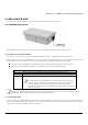

8000 Series - Hardware Overview and Installation
Tsunami
®
800 and 8000 Series - Hardware Installation Guide 83
Calculate:
Required RSL and fade margin to achieve link availability objectives. For more details on how to calculate RSL and fade
margin, please refer to the ‘Antenna Installation Guide’ and ‘Proxim Link Calculator’ that are available on the support
site at
.
Required path availability
Anticipated multi-path reflection points
Determine:
System Frequency Plan
Required transmission line types (like cable, waveguides) and lengths
Plan for:
Device’s continuous power consumption needs
Lightning protection and system grounding
Hardware mounting
Cable installation including egress
Pre-testing equipment (back-to-back test procedure)
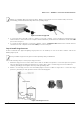
Step 2: Choose a Location
To make optimal use of the device, you must find a suitable location to install the hardware. Proxim recommends you do a site
survey, observing the following requirements, before mounting the hardware.
The location must allow easy disconnection of power to the radio, if necessary.
Ensure free flow of air around the hardware.
The radio device must be kept away from vibration and excessive heat.
The installation must conform to local regulations at all times.
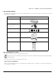
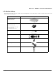
Step 3: Gather Required Tools
You should have the following tools available before installing the device:
Cross-tip screwdrivers
Large blade standard screwdriver
Spanner 13
Wire crimpers (if using connectors that are not pre-made)
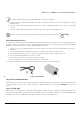
Step 4: Unpack the Product Package
Unpack the device and its accessories from the shipping box.
Please make a note of the Ethernet addresses, MAC addresses and the serial number. These addresses may be used
when configuring the device. Note that the serial number helps you to seek support from the Proxim’s Customer
support team.
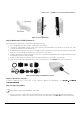
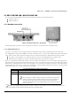
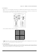
Step 5: Pole Mount the Device
1. To pole-mount the device to a 1 inch diameter pole, place the mounting bracket with its small V-Groove facing the
pole.
2. To pole-mount the device to a 2.5 inch diameter pole, place the mounting bracket with its large V-Groove facing the
pole.
3. Place the device with its rear side facing the pole, and screw the M8x80mm long screws along with the spring and
plain washers through the mounting bracket into the mounting holes of the device and tighten it to torque of 11
N.m/100 in-lbs.