TSUNAMI MULTIPOINT Connecting External Antennas CPN required Issue Date: 03/05/2003
Copyright and Service Marks Copyright © 2002 by Proxim Corporation. All rights reserved. No part of this manual may be reproduced without prior written permission from Proxim Corporation. The information contained in this manual is subject to change without notice. Proxim Corporation shall not be liable for errors contained herein or for incidental or consequential damages in connection with the furnishing, performance, or use of this manual or equipment supplied with this manual.
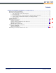
Contents CONNECTING EXTERNAL ANTENNAS TO THE BSU AND SU ................................................... 4 Planning for Antenna Installation ....................................................................................... 4 Reviewing the Installation Process ..................................................................................... 6 1. Test radios back-to-back and configure.................................................................... 6 2. Mount antennas .........................
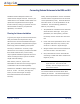
Connecting External Antennas to the BSU and SU Standard Tsunami Multipoint outdoor unit Finally, antenna polarization must be considered. models include integral antennas. However, SU The BSU and SU integral antennas use left-hand models 40100-xxxC and BSU models 40400-xxC circular polarization (LHCP). replace the integral antennas with a type-N with either linear or circular polarization can be female connector, letting you purchase and use considered.
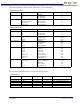
The following tables list antenna types, performance, and manufacturers. BSU Antenna Information Antenna Type Manufacturer Model Number Mid-Band Gain (dBi) Omni Telex MTI MTI 5830AN MT-482009/N MT-483003/N 7.
Prior to installation, determine the specific ▪ antenna location and type of mounting. The transmission line should be kept as short as possible so, when line-of-sight placement of antennas allow flexibility, it is always desirable Verify configuration settings (through the BSU Console) for proper configurations. ▪ Verify that the SU enters the network. ▪ Connect to services, if possible, to verify to locate the equipment closer to the antenna. network connection and configurations.
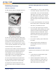
located indoors, locate the lightning arrestor Installing the Units at the building egress point. ▪ Follow the instructions in “Chapter 2. Deploying All lightning arrestors and transmission line must be properly grounded. 4. Connect Radios to Antennas and Power, including Grounding ▪ the Base Station Unit” in the Tsunami Multipoint Installation Manual to unpack, mount, and configure the BSU.
Establishing Connections Antenna Connection The BSU and SU radios are equipped with an N- Antenna Cabling Guidelines for 5.8 GHz Units ▪ Coaxial cables of 7/8-inch or larger diameter can exhibit moding at 5.8 GHz and are never type female connector at the antenna port. recommended. Also, some small diameter cable types, such as RG-8, have high loss or poor VSWR at these frequencies. If small diameter cables are required, be certain to keep the lengths of these cables as short as possible.
3. Pull the transmission line through the cable Be sure to use manufacturer-specified ducts, trays, or conduit (as required) to the connectors and termination tools, and follow antenna, while being careful not to kink or termination instructions precisely. Improper damage the transmission line in any way. transmission line terminations can cause excess losses and reflections that can lead to Note: RF transmission line must never be bent, many problems with the system.
BSU/SU Power Connections Refer to “Appendix D. Constructing Power and Ethernet Cables” in the Tsunami Multipoint Installation Manual for instructions. In cases of indoor installations, ensure that the antenna location is restricted and bear in mind the RF exposure requirements of the warning statement above. Antennas should be: Installing and Adjusting the Antenna ▪ specific to the site requirements. The installation information discussed in this section is generic.
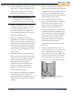
▪ It is critical that antenna alignment be When fine-aligning the BSU elevation: performed on one end of the link at a time, ▪ one plane at a time. ▪ One antenna should remain stationary at all times. ▪ Each end should be fine-aligned several times, until the planned RSL is reached. Adjust the elevation of the BSU antenna to maximize the RSL indication at the SU. ▪ Align the far-end antenna in the same manner, using the SU RSL indication.
Establishing a Connection Between the Units See “Aiming the SU” and “Confirming Network Activity” in “Chapter 3. Deploying the Subscriber Unit” of the Tsunami Multipoint Installation Manual for a description of how to verify the wireless connection between a BSU and SU.