Part Number 64352v1r2 Lynx.
Lynx.GX Installation and Management First Edition, January 2004 Copyright and Service Marks Copyright © 2004 by Proxim Corp. All rights reserved. No part of this book may be reproduced without prior written permission from Proxim Corp. The information contained in this book is subject to change without notice.
Lynx.GX Installation and Management Product Safety Instructions This product must be installed, used, and maintained by experienced telecommunications personnel only. When installed, this equipment is to be connected to a lightning/surge protection device that meets all applicable national safety requirements. WARNING! To avoid injury, risk of fire, and damage, do not connect this product directly to an antenna. Ensure that proper lightning isolation also is provided between this unit and other equipment.
Lynx.GX Installation and Management Contents PRODUCT SAFETY INSTRUCTIONS ............................................................................................................. 3 CONTENTS....................................................................................................................................................... 4 Figures ........................................................................................................................................................
Lynx.GX Installation and Management IDU/RFU Cable Connector and Pin Assignment...................................................................................... 81 RSL and GND Connectors on IDU ........................................................................................................... 82 RFU/Antenna Connector and Pin Assignment ......................................................................................... 82 RFU RSL/Tone and Pin Assignment ....................................
Lynx.GX Installation and Management Chapter 1. Introduction Proxim Corporation introduces the GX platform of wireless T1 or E1 radio products—Lynx.GX. The split-box design lets you install both units indoors, or one unit indoors (the IDU, or Indoor Unit) and one unit outdoors (the RF Unit, or RFU). The units can be mounted in a 19-inch or 23-inch rack; each unit is 1.75” high, occupying one rack unit (RU).
Lynx.GX Installation and Management PLANNING FOR INSTALLATION There are several planning factors to be considered prior to installing the radio system.
Lynx.GX Installation and Management Chapter 2. Installing the IDU and RFU The following sections describe how to install the GX radios. ▪ ▪ ▪ ▪ ▪ ▪ ▪ ▪ ▪ Step 1. Gather Required Tools (below) Step 2. Step 3. Step 4. Step 5. Step 6. Step 7. Step 8. Step 9.
Lynx.GX Installation and Management Additional tools may be needed for antenna and transmission line installation and antenna alignment as well as the lightning arrestor mounting and grounding. Consult the antenna manufacturer documentation and review “Installing and Adjusting the Antenna” on page 18. STEP 2. UNPACK SHIPPING BOX CONTENTS The boxes should be left intact and sheltered until arrival at the installation site.
Lynx.GX Installation and Management Lynx.GX 4xE1 Unbalanced (BNC) Lynx.GX 4E 5.8 GHz ISM System Hi, Model 301-51850-30H0 (Item #64751) Low, Model 301-51850-30L0 (Item #64749) Item # Description Item # Description 64750 Lynx.GX 4E1 Indoor Unit, Unbal., BNC 64750 Lynx.GX 4E1 Indoor Unit, Unbal., BNC 62138 Lynx.GX 5.8 GHz Hi RF Unit 62137 Lynx.GX 5.
Lynx.GX Installation and Management GX Installation Kits Item Contents Qty.
Lynx.GX Installation and Management Required Equipment for Test Back-to-back testing must be performed with both radios at the same location.
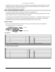
Lynx.GX Installation and Management Link Testing Link testing is the preferred way to evaluate a radio link's performance. It can be performed from end-to-end or in link test mode (which tests both directions of the radio path). The following figure illustrates a typical test configuration (which may include the radio’s path instead of in-line attenuators). Figure 2. Link Testing When performing testing, verify all configuration settings.
Lynx.GX Installation and Management Only one loopback can be enabled per link at a time; that is, only one channel can be tested at a time and configuring a channel in loopback disables the current loopback. The front panel and Web interface loopback LED on the near-end and far-end radios informs the operator that the radio is configured in loopback mode. STEP 4. INSTALL THE RADIO UNITS There are two primary ways to install the radio system.
Lynx.GX Installation and Management To rack-mount the IDU and RFU: 1. Gather all the parts contained in the GX IDU Installation Kit. 2. Set the unit on a flat surface and, using a screwdriver, remove the front screws on each side of the unit that match up to the holes of the rack mounting flange. You must remove these screws to prepare the unit for bracket attachment. 3.
Lynx.GX Installation and Management 4. Position the radio in the rack and align the holes in the mounting bracket with the holes in the rack. Two screws for each bracket should be used into the rack (these screws are not included).
Lynx.GX Installation and Management Installing the RFU Outdoors The outdoor RFU installation consists of these tasks: ▪ ▪ Installing the mounting brackets and mounting plate onto the pole (using two band clamps). Mounting and securing the RFU on the mounting plate. Notes: (1) Installing the RFU outdoors requires the use of the optional GX RF UNIT Outdoor Mounting Kit (Proxim part ACC-GX-RF-2, item number 61688), sold separately.
Lynx.GX Installation and Management Mounting the RFU 1. Orient the RFU for mounting onto the mounting plate so that the connectors are pointed down and the heatsink fins are facing away from the bracket. 2. Insert carriage bolts into the upper holes of the RFU with the head of the bolt facing the flat side (back) of the RFU.
Lynx.GX Installation and Management Mounting the Antenna This section describes how to permanently mount the antenna to the mast, pole, or tower, and how to attach the antenna to the RFU. The antenna must be mounted outdoors on a tower, building roof, or other location that provides line-of-sight path clearance to the far-end location. In general, antennas smaller than two feet in diameter, or one-foot panels, are not recommended for use with these radios.
Lynx.GX Installation and Management If you cannot set a heading marker sufficiently far away (for example when on a city building roof), obtain a rough azimuth setting by sighting along the antenna feed or based upon compass measurements made during the path planning stage. Note: Use the instructions provided by the antenna manufacturer to verify that both antennas are on the same polarization; otherwise, the RSL will be approximately 25 to 30 dB below the calculated level.
Lynx.GX Installation and Management Checking RSL Against Predicted Results There are two RSL voltages that can be read off the radio. ▪ ▪ The IDU front panel has an RSL Test Point for a voltmeter probe. The RFU also has a voltage test point at the BNC connector. Both the IDU RSL voltage and the RFU RSL voltage readings are identical: They can range from 0.9 volts for –90 dBm to 0.05 volts for –5 dBm. The RSL voltage is -Volts RSL (mV)/10 or -10mV per dBm, so that the readings can range from 0.
Lynx.GX Installation and Management STEP 6. ESTABLISH CONNECTIONS This section discusses antenna connection, RF coaxial cable connection, IF transmission line connection, grounding, and power connections. Helpful Hints—Lines and Connections ▪ ▪ Use proper transmission line. ▪ ▪ ▪ ▪ ▪ ▪ Be careful with the bend radius and never kink the transmission line. Proper termination is critical, especially at 5.8 GHz. Follow manufacturer’s instructions and use proper tools and connectors.
Lynx.GX Installation and Management Antenna Cabling Guidelines for 5.8 GHz Units ▪ Coaxial cables of 7/8-inch or larger diameter can exhibit moding at 5.8 GHz and are never recommended. Also, some small diameter cable types, such as RG-8 or LMR-400, will have high loss or poor VSWR at these frequencies. If small diameter cables are required, be certain to keep the lengths of these cables as short as possible and always properly terminate these cables. ▪ For wave guide transmission at 5.
Lynx.GX Installation and Management To prepare the RF transmission line or the RFU-to-IDU cable (experienced or skilled technician only): 1. Cut a cable to the proper length (allowing some excess for service loops) that will connect the RFU to the building egress point. Terminate both ends with TNC-Male connectors. 2. Repeat this process for the cable that will connect to the lightning surge protector outside the building egress point and the equipment.
Lynx.GX Installation and Management Connecting IF Coax Cable The radio can be installed with the RFU mounted indoors above the IDU in a 19-inch or 23-inch rack, or mounted outdoors onto the pole-mounted bracket (included). ▪ ▪ For indoor mounting, a short IF coaxial cable is included in the accessory kit to connect the IDU to the RFU. For indoor/outdoor mounting, a long IF coaxial cable is required to connect the IDU to the RFU outdoors.
Lynx.GX Installation and Management Be sure to connect the return to ground at the DC power plug and make sure that all equipment is grounded to proper station earth ground. Negative DC Power Input Pin Assignment (20 to -63 VDC) Pin Number Function 1 Power (–DC) 2 Ground 3 Return (+DC) Positive DC Power Input Pin Assignment (+20 to +63 VDC) Pin Number Function 1 Return (–DC) 2 Ground 3 Power (+DC) Note: Each radio terminal block must be fused externally with an 5-Amp maximum fuse.
Lynx.GX Installation and Management Grounding WARNING! This equipment is intended to be grounded. If you are not using the power supply provided by Proxim Corporation, you must connect the grounding conductor of your power source to the grounding terminal located on the units; or, connect an grounding conductor between the unit's grounding terminals and your grounding point. For safe operation, always ensure that the units are grounded properly per the following figure.
Lynx.GX Installation and Management STEP 8. ESTABLISH A LINK BETWEEN THE RADIOS Follow these steps to establish a link between the radios: 1) Connect the transmission line to the antenna and feed it to the RFU location. Connect the opposite end of the transmission line to the N-type female connector located on the RFU through a lightning arrestor. If the RFU is mounted indoors or in a shelter, the lightning protection should be located at the cable egress point.
Lynx.GX Installation and Management Often, an RF power meter has a limit to the input power it can measure without damage. Proxim advises you place a calibrated fixed value RF attenuator (typically 20 dB or more) between the radio and the power meter to ensure proper operation and safety for the RF power meter. The value of this fixed attenuation then can be added to the value of the RF power meter reading to obtain the actual transmitter output power.
Lynx.GX Installation and Management Helpful Hints—Checking RSL Against Predicted Results ▪ Is the RF Link LED red? º º ▪ Does the measured RSL at both ends closely match the predicted value? º º º º º º ▪ If so, keep aligning the antennas. If not (or green), the radios are talking! If too strong, this is probably OK; the transmitter power may be higher than originally planned. If not strong enough, keep aligning.
Lynx.GX Installation and Management STEP 9. ESTABLISH NEAR-END TO FAR-END COMMUNICATIONS USING ORDERWIRE (OPTIONAL) To establish near-end to far-end communications using orderwire: 1. Connect telephones to the near-end and far-end radios. Using a standard RJ-11 telephone cable, connect a standard electronic telephone (a touch tone phone, complete with dialer, or DTMF phones) to the Orderwire connector on the radio front panel. This connector is wired identically to a standard two-wire telephone jack.
Lynx.GX Installation and Management Chapter 3. Managing the Lynx.GX You can configure and manage the radios using any of the following methods: Web Interface Using a Netscape® or Windows® Internet Explorer browser, you can configure and manage the unit using a Web-based management interface. This management method includes all configuration parameters and monitoring information.
Lynx.GX Installation and Management MANAGING WITH THE WEB INTERFACE Minimum Computer Requirements for NMS The client PC should satisfy the following minimum requirements: ▪ ▪ ▪ ▪ CPU Processor speed greater than 1 GHz Web Browser: Internet Explorer, version later than 5.0; Netscape 7.
Lynx.GX Installation and Management Figure 4. Daisy Chaining NMS Connections at a Hub Location The next few pages describe how to access the Web Interface and the configuration and management available. Initial Log-On To access the Web Interface: 1. At your browser address field enter http://10.0.0.1 (or your previously set IP address) to open the Logon window. Chapter 3. Managing the Lynx.
Lynx.GX Installation and Management 2. Enter the following administrative logon username and default password (or your previously set password) in the corresponding fields on the logon page: Username: managers Password: managers The monitoring logon username and default password are: Username: operator Password: operator The radios ship from the factory with the default user name and password, as shown above.
Lynx.GX Installation and Management Initial Configuration The default settings of all Lynx.GX radios are: IP Address: 10.0.0.1 Subnet Mask: 255.0.0.0 Gateway Address: 0.0.0.0 The next three steps should be accomplished while both radios are on a test bench. Additional details follow. Step 1: Change the PCs IP address to the same subnet as 10.0.0.x. This allows you to address the local radio. Step 2: Using the CLI, change the IP address, subnet mask, and default gateway of the two radios.
Lynx.GX Installation and Management This example uses the default addresses of 10.0.0.1 for the near end radio, and 10.10.0.x for the far end radio. This is a temporary static route. To make it permanent, add this as a batch file to run at system startup. The GX radios use RIP to learn routes automatically in your network. Remember, this extended NMS network is available only while the wireless link is up.
Lynx.GX Installation and Management Basic Tasks with the Web Interface The following sections introduce you to the Web Interface and the tasks that can be accomplished with each window. For more in-depth information about the Web Interface windows, see “Web Interface Windows and Field Descriptions” on page 56.
Lynx.GX Installation and Management Viewing Radio Information Use this tab: To do this: Device Tab on page 56 Access radio information, such as model and serial numbers, data rate and frequency, interface type, and software version levels. The fields in this window are not configurable. Window Modifying T1 / E1 Channel Interface Configurations Intf Cfg Tab on page 57 Modify the T1 or E1 channel interface configurations, including line build-out, line code, and loopback configuration. Chapter 3.
Lynx.GX Installation and Management Viewing the Current Near and Far Status Status Tab on page 59 View the current Near and Far status for the selected unit, including BER, errored seconds, RSL, elapsed time since reset, and temperature. You also can track the RSL reading of the radio over time by clicking the RSL Log button on the Status window. The fields on this window are not configurable. See “RSL Log” on page 60 for more information.
Lynx.GX Installation and Management Changing Passwords, System Date and Time, SNMP Community Strings, and IP Address Admin Tab on page 64 Change the system passwords, system date and time, SNMP community strings, and radio IP address information. You can also enable the built-in Spectrum Analyzer to check for transmission sources that the radio can receive and to determine whether these emitters could be a source of possible interference (click the Spectrum Analyzer button on the Admin window).
Lynx.GX Installation and Management Viewing All or Selected Status and Alarms Log Tab on page 62 View all or selected status and alarms for the radio. You can view alarms of all levels or selected levels and greater. Viewing Proxim Support Information Contact Tab on page 64 View Proxim Support information (see “Technical Support” on page 100) Chapter 3. Managing the Lynx.
Lynx.GX Installation and Management Uploading Software You can upload the most recent version of the application software. To upload a file: 1. Download the most recent software from http://www.proxim.com/support/. 2. Connect the PC with the new software to the radio terminal through the NMS. 3. At your browser’s address field, enter http:///upload.htm, or select File Upload from the Admin tab. (For factory default, use 10.0.0.1 for the IP address.) 4.
Lynx.GX Installation and Management MANAGING WITH SNMP The radios support SNMP version 2C and earlier. All SNMP traffic, including traps, SET commands, and GET commands, are sent and received through the NMS whether locally or through the in-band PPP link. See “Planning NMS Configuration” on page 33 to configure the NMS network. Requirements ▪ A copy of the Proxim MIB files are required to configure and manage the radios using SNMP. There is a generic MIB for all GX radios (g4_generic.
Lynx.GX Installation and Management 5. Enter gxHelp to view available commands, as shown in the following figure: To end a Telnet session use the logout command. A config port session is unavailable until any telnet session has ended. CLI Commands These are the CLI commands you can use: gxHelp ............................................... Shows system information and list of commands. getPerf ............................................. Snapshot of the performance data. setIP(“IpAdr”) ................