
User Manual Part 1

Lynx.GX Installation and Management
Required Equipment for Test
Back-to-back testing must be performed with both radios at the same location. The following test equipment is
required:
▪ DC power source capable of supplying approximately 200 Watts (total) to the radios (or two radio AC
adapters)
▪ One low-loss coaxial cable, N-to-N male
▪ One (or more) coaxial in-line fixed attenuators, 50 to 100 dB total attenuation
The following test equipment may also be useful for further testing of the radio:
▪ Bit Error Rate (BER) tester
▪ Variable RF attenuator (60 dB range or more, rated for the proper frequency, 5.8 GHz) or several fixed
attenuators totaling 100 dB.
▪ RF power meter
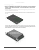
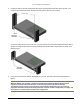
Back-to-Back Test Configuration
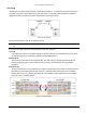
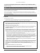
When the equipment is connected as shown in the following figure, both radios should have no alarm
conditions. (Data Input and AIS OUT are exceptions, if any of the T1/E1 channels are not connected.) If these
conditions have been met, it is likely that the radio is operating in accordance to specifications. If errors or
alarms occur during this test, verify alarm status. If alarms or errors are still present, one or both of the radio
terminals is likely to be faulty.
Figure 1. Back-to-Back Test Configuration
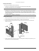
It can be helpful to insert a variable RF attenuator between the radios to fade down the path to determine that
the threshold specification is being met. You can run the threshold tests in both directions to isolate the radio
problem (if any). See “Link Testing” on page 13 for more information.
You can use an RF power meter to individually test each radio’s output power to test the transmitter functions.
You can also use the radio’s output transmitter attenuation to help precisely lower the link to threshold level after
inserting attenuation.
If the transmitter output power has been verified (by the mathematics of the back-to-back test or by a power
meter) and the threshold is not meeting specification, the side whose threshold is diminished is the likely radio at
fault. Swapping IDUs from one end to the other can help determine whether the problem is with the IDU or the
RF Unit.
WARNING!
The radios will be damaged if appropriate attenuation is not supplied between radios. You must provide
a minimum of 50 dB between the two radios. At 50 dB attenuation, output power can be left at maximum
output power.
Chapter 2. Installing the IDU and RFU 12