
User Manual Part 1

Lynx.GX Installation and Management
If you cannot set a heading marker sufficiently far away (for example when on a city building roof), obtain a
rough azimuth setting by sighting along the antenna feed or based upon compass measurements made during
the path planning stage.
Note: Use the instructions provided by the antenna manufacturer to verify that both antennas are on the same
polarization; otherwise, the RSL will be approximately 25 to 30 dB below the calculated level.
Because maximizing the receive RF signal level at each end of the radio link is critical, most antennas also
require fine alignment using an operating link.
Once the coarse alignment is completed at both ends, the link can be powered and some level of reliable
communication established. The voltage at the radio test point can be measured with a DVM to determine the
relative receive RF signal level.
Note: Be sure to read “Power Connections” on page 27 prior to powering up the radios.
Fine Alignment
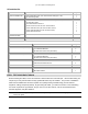
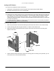
When fine-aligning the antenna:
▪ Adjust the azimuth and then the elevation of the local antenna to maximize the RSL voltage.
▪ Align the far-end antenna in the same manner, using the RSL voltage of its local RFU.
Helpful Hints—Antenna Alignment
▪ Rough align antenna azimuth and elevation based upon path planning (using compass bearing or milestone
sighting, telescopic sight, binoculars, and so on).
▪ Apply power to both ends of the radio system
▪ Use a Digital Volt Meter (DVM) to read the radio’s RSL voltage provided on the RFU to peak antennas. Or,
use the RSL reading from the IDU’s front panel test point. (See “RSL / GND” in “Front Panel LED
Descriptions” on page 73.)
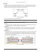
▪ When aligning antennas, if the RFU is located indoors or distant from the antenna location, you may want to
run wires or a cable from the RSL test point on the RFU to the antenna location so that the voltmeter
reading or audio device is directly visible and audible to the technicians aligning the antenna. Alternatively:
º The RSL value can be provided by a ‘verbal relay’ or by two-way radio (or similar communications
device) from the radio location to antenna alignment personnel.
º The RFU (and IDU, if necessary) can be taken to the antenna location temporarily for the purposes of
antenna alignment. An additional short transmission line jumper may be required for this approach,
along with TNC-to-N adaptors at each end of the primary transmission line. If this approach is used, the
actual RSL when alignment is completed is higher than that planned (due to the shorter transmission
line). Verify the desired RSL once the radio system is mounted as originally planned.
º Coaxial couplers can be placed temporarily at each end of the primary transmission line so the RSL
voltage is sent to the antenna location.
▪ A cellular telephone or two-way radio can be useful for coordinating alignment activities between both ends
of the link. You can use an orderwire telephone for end-to-end voice communications once the units are
synchronized. Synchronization usually can be accomplished by coarse alignment alone. After
synchronization, you can use the orderwire phones to communicate between radio sites for antenna fine
alignment.
▪ Make sure antenna polarization is the same at both ends.
º Adjust alignment of one antenna at a time, one plane (azimuth vs. elevation) at a time.
º Adjust each end multiple times until predicted RSL is achieved.
Chapter 2. Installing the IDU and RFU 20