Lynx.GX Installation and Management Appendix A. Installation Planning Prior to installing the radio system, be sure you have considered the following factors.
Lynx.GX Installation and Management Clearing less than 60% of the 1st Fresnel zone will result in excess signal loss due to diffraction, in addition to the calculated free-space loss. Excessive antenna height resulting in clearance of the 2nd and higher order Fresnel zones sets up the likelihood of multi-path reflection outages. The higher the number of the “cleared” Fresnel zones, the more likely that a system multi-path reflection outage will occur when atmospheric refractivity changes.
Lynx.
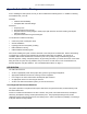
Lynx.GX Installation and Management Earth Curvature Formula (international) Clearance for terrain can be determined from accurate topographic maps (the height of trees and/or buildings must be considered). Alternatively, the path can be surveyed along the direct route. Clearance for earth curvature can be calculated for various "K" factors using the formula: h = d1 x d2 / 12.
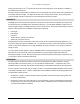
Lynx.GX Installation and Management Reflection Point (international) The formula for calculating the position of the reflection point on a path is for K = 4/3 h1/d1 – d1/17 = h2/d2 – d2/17 for K = 2/3 h1/d1 – d1 /8.5 = h2/d2 – d1/8.5 for K = ∞ d1 = D • h1/(h1 – h2.) where: h is in meters d and D are in kilometers (The K factor allows for consideration of atmospheric conditions by allowing for the path of the beam, relative to the earth.
Lynx.
Lynx.GX Installation and Management In the USA and Canada, this model radio can be installed with any gain directional antennas, as there is no Effective Isotropic Radiated Power (EIRP) limit for the application of these systems for fixed point-to-point applications. In other countries, EIRP limits may apply. In the case of EIRP limits, use the lesser of either (Pout - L1+ G1) or the EIRP limit within the previous equation. You should check this equation in both directions to assure legal application.
Lynx.GX Installation and Management PLANNING FOR AND SELECTING IF CABLE The radio can be installed with the RFU mounted indoors above the IDU in a 19-inch (or 23-inch) rack, or mounted outdoors onto the pole-mounted bracket (sold separately). For indoor mounting, a short IF coaxial cable is included in the IDU accessory kit to connect the IDU to the RFU; the cable is TNC (male) to TNC (male), about 12 inches in length.
Lynx.GX Installation and Management PLANNING FOR ANTENNA AND RF TRANSMISSION LINE INSTALLATION In general, the larger the antenna used with the radio, the better the link performs. Larger antennas have narrower beamwidth and higher gain, which yield better link performance (higher fade margin, better availability) and improve immunity to interference (due to the narrower beamwidths).
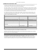
Lynx.GX Installation and Management Antenna Manufacturer Information Antenna Type Manufacturer Model Number Mid-Band Gain (dBi) 1-foot flat panel Tripoint Global Andrew RFS DFPD1-52 FPA5250D12-N MA0528-23AN 23.5 23.6 23.0 2-foot flat panel Tripoint Global Andrew RFS DFPD2-52 FPA5250D24-N MA0528-28AN 28.0 28.2 28.0 2-foot parabolic Tripoint Global Tripoint Global Radio Waves Andrew RFS QF2-52 HQF2-52 SP2-5.2 P2F-52 SPF2-52A 28.5 28.1 28.3 29.4 27.
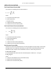
Lynx.GX Installation and Management Appendix B. Web Interface Windows and Field Descriptions DEVICE TAB—ACCESSING RADIO INFORMATION You can access radio information by clicking the Device tab. The Device tab is illustrated in the following figure, which provides information about a Lynx.GX 8T. A description of each field follows the figure. Device Window Field Descriptions Model Number The model number of the radio being managed. IDU Serial Number The IDU serial number of this system.
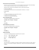
Lynx.GX Installation and Management INTERFACE CONFIGURATION TAB—MODIFYING T1/E1 INTERFACE CONFIGURATIONS To modify the T1 or E1 channel interface configurations, click the Intf Cfg tab. The Intf Cfg page is shown in the following figure, which depicts a Lynx.GX 8T. A description of each column in the Intf Cfg page follows the figures. After making your changes, click the Apply button to implement and save your changes. The Get Defaults button lets you see the default settings.
Lynx.GX Installation and Management After entering any configuration changes, click on the Apply button. The Default button installs the default settings for all entries but does not apply them until the Apply button is clicked. Any changes outside the range of acceptable values is identified for the user (with a “Failed to change configuration(s)” message) and the changes fail to apply.
Lynx.GX Installation and Management STATUS TAB—VIEWING CURRENT STATUS To view the current Near and Far status for the selected unit, click the Status tab. You can click the Near or Far Reset History buttons to clear all data for the corresponding radio, which is useful for resetting the time stamp, such as after installation. A description of each row follows the figure.
Lynx.GX Installation and Management Viewing the RSL Log A window such as the following is displayed when you click the RSL Log button from the Status window; this is an RSL log page at 1-minute intervals. This feature is useful for tracking the RSL reading of the radio over time to view any degradation of performance, and to correlate any alarms recorded in the Alarm log. You can determine the frequency at which entries are displayed from the drop-down box at the bottom left of the window.
Lynx.GX Installation and Management ALARMS TAB—MONITORING LINK STATUS Click the Alarms tab to monitor both near-end and far-end link alarm status. Field descriptions follow the figures. Note that the orientation of the alarms matches the position of the connectors on the front panel. These alarms contain some more specific detail than the Front Panel display, and are helpful in determining possible problems.
Lynx.GX Installation and Management LOG TAB—VIEWING STATUS AND ALARMS You can view all or selected status and alarms for the radio when you click the Log tab. You can choose to view alarms of all levels or selected levels and greater. To update the information, click Refresh at the bottom of the page. Click Reset to clear the log. Log Window Field Descriptions Date/Time The date and time the status/alarm was reported. Severity The severity of the alarm. Description A description of the status/alarm.
Lynx.GX Installation and Management Severity Message Description for Alarm Status CRITICAL Radio Sync The radio is not communicating to the far end. MAJOR Major relay alarm The major relay is in alarm (a MAJOR alarm condition exists). MAJOR Link ID mismatch The link security IDs do not match within the last minute. MAJOR BER 10-3 Error The wireless link BER has exceeded 10-3. MAJOR RF Unit Synth Error The RF UNIT Synthesizer has failed.
Lynx.GX Installation and Management CONTACT TAB—VIEWING SUPPORT INFORMATION Click the Contact tab to view Proxim Support information (see “Support” on page 100). If you are connected to the Internet, you can click on the URL or on the Proxim logo to open Proxim’s Internet site, and you can click on the e-mail address to open an e-mail window addressed to Proxim Technical Support.
Lynx.GX Installation and Management Admin Window Field Descriptions Monitoring Password Enter the monitoring password (8 to 15 characters). This is the password for “operator” on the log-in page. To change the password, you must re-enter the password two times. The default is “operator.” Configuration Password Enter the configuration password (8 to 15 characters). This is the password for “managers” on the log-in page.
Lynx.GX Installation and Management The current status of the Spectrum Analyzer is indicated on the bottom. When this menu is first turned on the analyzer is not running. To start the analyzer, click on the Start button. The Spectrum Analyzer interrupts traffic on the near end because it is analyzing the spectrum. The far-end radio is still receiving from the near-end transmitter. Click Start to run the Spectrum Analyzer; it completes a scan within a few minutes and displays the data as it is processed.
Lynx.GX Installation and Management There are 25 bars across the screen, representing 25 measured points spaced 2 MHZ apart from the left of the display (in this example, 5.721 GHz) to the right of the display (5.769 GHz). The height of the red bar indicates the highest level of the received signal at that frequency. The height of the green bar is the lowest level of the received signal at that frequency.
Lynx.GX Installation and Management A B C Appendix B.
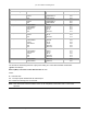
Lynx.GX Installation and Management Appendix C. Lynx.GX Front Panel and Connections MODELS This information in this appendix applies to the following Lynx.GX models. Model Number Item Number 301-51850-10L0 301-51850-10H0 62291 62292 301-51850-20L0 301-51850-20H0 Ports Frequency Band Compliance 4 T1 ports RJ-48C 5.8 GHz ISM 62294 62295 4 E1 ports, balanced RJ45 5.8 GHz ISM 301-51850-30L0 301-51850-30H0 64749 64751 4 E1 ports, unbalanced BNC 5.
Lynx.GX Installation and Management 8T Output Power ................................... ≥ 23 dBm Channel Pairs................................... 2 Main Interface Connectors ............... RJ-48C with Activity LED Aggregate Capacity.......................... 13.5 Mbps Line Code/Channel .......................... AMI/B8ZS Line Build-out/Channel..................... 0-655 feet, selectable 8E Balanced Output Power ................................... ≥ 23 dBm Channel Pairs...................................
Lynx.GX Installation and Management LYNX.GX FRONT PANEL The IDU front panel can be thought of as having three distinct parts. ▪ The left portion of the IDU contains the connection for the RF Unit, the DC power connection, and the RSL and GND test points. ▪ The middle portion of the IDU contains connectors specific to the Lynx.GX model. ▪ The right portion contains LEDs, CONFIG, ALARMS, and ORDERWIRE connections, and a FAR END push button switch.
Lynx.GX Installation and Management 8xT1 or 8xE1 Connections The center portion of the front panel for the Lynx.GX 8T / Lynx.GX 8E is illustrated in the following figure. 16xT1 Connections The center portion of the front panel for the Lynx.GX 16T is illustrated in the following figure. FRONT PANEL COMMON CONNECTORS, INDICATORS AND CONTROLS To RFU This is an RF TNC female connector. This connector is used to connect the IDU to the RFU.
Lynx.GX Installation and Management There are two external input alarms, independent of the relay outputs available. From the SysCfg page, you can set whether an open or closed condition produces an alarm. See the table of alarms in “Log Tab: Viewing Status and Alarms” on page 62. See “Connectors and Pin Assignments” on page 46 for ALARM port connector information.
Lynx.GX Installation and Management FAR END When the LED on this button is red, alarms exist on the far-end radio. Press and hold the button to view those alarms on this radio’s front panel. If the far-end radio is not available, such as when the link is down, all LEDs flash red. Note: Pressing and holding this button while powering on the radio resets the IP address settings and passwords to default values.
Lynx.GX Installation and Management Appendix D. Connectors and Pin Assignments This section describes the radio port connectors and pin assignments for the IDU (Indoor Unit) and RFU (Radio Frequency Unit). IDU MAIN TRAFFIC T1/E1 CONNECTORS The main traffic ports for T1 or E1 connections appear on the front panel as multiple 8-pin modular jack connectors wired per RJ-48C.
Lynx.GX Installation and Management IDU VF PORT The front panel VF (Voice Frequency) port supports standard audio interfaces (600 ohm balanced, 0 dBm maximum level) on an 8- pin modular jack as shown below. This port can be connected to an external orderwire unit, and is bridged to the Orderwire RJ-11 connector. The green LEDs on the VF port have no function. The front view is illustrated. Figure 6.
Lynx.GX Installation and Management IDU AUX DATA PORT CONNECTOR (DCE PORT) The front panel Aux (Auxiliary) Data Port supports EIA-561 (electrical wiring standard) serial data on an 8-pin modular jack as shown below. The data rate is user selectable to 2400, 4800, 9600, or 19,200 bps. The asynchronous data is configured for 1 start bit, 8 data bits, no parity, and 1 stop bit. The green LEDs on the Aux Data port have no function. The front view is illustrated.
Lynx.GX Installation and Management IDU NMS PORT CONNECTORS The two front panel NMS (Network Management System) Port connectors (NMS1 and NMS2) support 10/100BaseT Ethernet serial data using two 8-pin modular jack connectors. Shown below is the wiring for each connector per USOC 568B. Two jacks permit bridging to other Ethernet devices without the need for an additional Ethernet hub or switch.
Lynx.GX Installation and Management IDU ALARM PORT CONNECTOR External alarm outputs are provided using the 9-pin, D-type (DB-9) ALARM female connector. Two Form C alarm relays capable of switching 30 VDC at 1A are provided. Both relays are energized in the normal state and de-energized in the alarm state. The two relay alarms are: ▪ Major or “Out-of-Service” alarm is activated by any red alarm. This is also indicated by the “bar” alarm indicator on the GUI.
Lynx.GX Installation and Management IDU CONFIGURATION PORT CONNECTOR (DTE PORT) Configuration (CONFIG) port connections to modems, computers, or terminals, as well as auxiliary data connections, are made using a 9-pin, D-type, female connector, compliant to EIA-574 wiring. The CONFIG port is configured as a DTE (Data Terminal Equipment) so a null modem cable (pin 2 is connected to pin 3) is required when connecting to a DTE such as a standard PC Serial COM port. Figure 10.
Lynx.GX Installation and Management IDU ORDERWIRE PORT CONNECTOR The IDU front panel Orderwire telephone port supports connection to standard electronic ringer telephones on a 6-pin RJ-11 modular jack as shown below. The center two pins (pins 3 and 4) are used for the Tip and Ring. Telephones with RJ-11 modular plugs can be 6-, 4-, or 2-pin modular plugs. The center two pins are used on the phone regardless of the number of pins on the modular plug . Figure 11.
Lynx.GX Installation and Management RSL AND GND CONNECTORS ON IDU The RSL (Received Signal Level) and GND (Ground) front panel test points are both single connection female test points that permit insertion of a 0.062” test probe pin from a VOM (Volt Ohm Meter). The test point is located on the IDU just below the “Proxim” logo and the radio type on the unit. Figure 13.
Lynx.GX Installation and Management RFU RSL/TONE AND PIN ASSIGNMENT The RFU (RF Unit) is provided with a BNC (Bayonet Neill Concelman) connector that provides a dual function for assisting in antenna installation and alignment: ▪ Provide a high impedance drive DC voltage level corresponding with the RSL (Received Signal Strength). A standard DVM (Digital Volt Meter) is used for this purpose. ▪ Provide a low impedance drive AC voltage tone that indicates the RSL.
Lynx.GX Installation and Management Appendix E. Spares and Accessories The following optional spares and accessories are available for purchase for your Lynx.GX radio. Order # Model # Product Description Contents 67265 301-52000-H GX RF UNIT SPARE 5.8GHz ISM HIGH A single RFU 5.8GHz ISM high with no accessories 67264 301-52000-L GX RF UNIT SPARE 5.8GHz ISM LOW A single RFU 5.
Lynx.GX Installation and Management Appendix F. Lynx.GX Specifications LYNX.GX 4T/4E (5.8 GHZ) SPECIFICATIONS Product Information Lynx.GX 4T1 Lynx.GX 4E1 Product Part Number 301-51850-10L0, -10H0 301-51850-20L0 -20H0 (balanced) 301-51850-30L0 -30H0 (unbalanced) Frequency Band of Operation 5.725 to 5.850 MHz Digital Capacity 4 x T1 (4 x 1.544 Mbps) 4 x E1 (4 x 2.048 Mbps) T/R Spacing 85 MHz 85 MHz System and Transceiver Specifications Lynx.GX 4T1 Lynx.
Lynx.GX Installation and Management LYNX.GX 8T (ISM) SPECIFICATIONS Product Information Product Name Lynx.GX 8T1 Product Part Number 301-51145-10L0, -10H0 Frequency Band of Operation 5.725 to 5.850 MHz Digital Capacity 8 x T1 (8 x 1.544 Mbps) T/R Spacing 85 MHz Emission Designator 13M4G7D System and Transceiver Specifications Frequency Range 5.725 – 5.850 GHz Modulation type DSSS QPSK System Gain 112 dB Aggregate Data Rate 13.5 Mb/sec, full-duplex Transmit Output Power ≥ +23.
Lynx.GX Installation and Management LYNX.GX 8E (ISM) SPECIFICATIONS Product Information Product Name Lynx.GX 8E1 Product Part Number 301-51145-20H0, -20L0 Frequency Band of Operation 5.725 to 5.850 MHz Digital Capacity 16.384 Mbps (8 x E1) T/R Spacing 85 MHz Emission Designator 28M4G7D System and Transceiver Specifications Frequency Range 5.725 to 5.850 MHz Modulation type DSSS QPSK System Gain 110 dB Aggregate Data Rate 27.5 Mb/sec Transmit Output Power +23.
Lynx.GX Installation and Management LYNX.GX 16T SPECIFICATIONS Product Information Product Name Lynx.GX 16T1 Product Part Number 301-52290-10L0 (Low Band), -10H0 (High Band) Frequency Band of Operation 5.725 to 5.850 MHz Digital Capacity 16 x T1 (16 x 1.544 Mbps) T/R Spacing 85 MHz Emission Designator 28M1G7D System and Transceiver Specifications Modulation type DSSS QPSK System Gain 109 dB Aggregate Data Rate 27.5 Mb/sec, full-duplex Transmit Output Power ≥ +23.
Lynx.GX Installation and Management DETAILED LYNX.GX SPECIFICATIONS General System Parameters Operating Frequency 5.8 GHz ISM band Product Configuration Split box IDU + RF Unit (RFU with outdoor option) Digital Capacity Up to 16 x T1 (16 x 1.
Lynx.GX Installation and Management Network Management System Connector RJ-45 (modular jack) 2 each NMS 1 10/100 Base-Tx NMS 2 10/100 Base-Tx Test Point RSL Voltage = -10mV per RSL (dBm); Range = 0.9 to 0.
Lynx.
Lynx.GX Installation and Management IDU Controls Far End Pushbutton Yes NMS Connector LEDs NMS 1 Right LED = Link: Green = Link On; Off = Link Off Left LED = Duplex: Green = Full; Flashing=Half w/collisions; Off = Half Duplex NMS 2 Right LED = Link: Green = Link On; Off = Link Off Left LED = Duplex: Green = Full; Flashing=Half w/collisions; Off = Half Duplex Appendix F. Lynx.
Lynx.GX Installation and Management Appendix G. Troubleshooting This chapter provides information about: ▪ ▪ ▪ ▪ ▪ ▪ ▪ Changing Frequency Plans Counteracting and Evaluating Interference Troubleshooting data stream errors and interference Troubleshooting alarms Measuring radio function Troubleshooting radio management tools Repair policy CHANGING FREQUENCY PLANS The radio frequency selections are listed in “Channel Plans” on page 70.
Lynx.GX Installation and Management Narrow Beam Antennas (High Gain) This is the next most effective countermeasure. Narrow-beam antennas ensure that the transmitted power is sent in a single direction; this minimizes the possibility of causing interference inadvertently to other users. Narrow beam antennas also reject off-azimuth signals being received from potential sources of interference and have high gain, which boosts desired receive levels and improves the carrier-to-interference signal level.
Lynx.GX Installation and Management Use of a Spectrum Analyzer to Evaluate Potential Interference Connecting to the antenna and using “peak hold” on a spectrum analyzer, the spectrum across the receive frequency range of the radio can be swept and any signals being received at levels above the radio's specified threshold identified.
Lynx.GX Installation and Management Recommended Actions ▪ ▪ Check and Verify data interface wiring Follow the troubleshooting instructions described in “IDU Fail Alarms.” RF Link Alarms This LED indicates that the demodulator function is not synchronizing with the intended received signal.
Lynx.GX Installation and Management Power Adjustment If only one end has low RSL, this could be caused by low transmit output power from the opposite end radio. Verify that the transmitter output power of the radio opposite to the low RSL receiver has been set in accordance to path calculations or EIRP restrictions (where applicable). WARNING! Power adjustment must be performed by professional installation personnel only. Tx Power can be viewed or adjusted from the Sys Cfg web page.
Lynx.GX Installation and Management RF Unit, Cable, and IDU Alarms These LEDs indicate a known problem with the radio hardware. Possible Causes ▪ ▪ ▪ RF Unit hardware failure, such as amplifier or pre-amp circuits IF cable shorted IDU hardware failure Recommended Actions 1. Remove power from the unit. 2. Check to make sure power supply voltages are within specification. 3. Reapply power to the unit, even if the voltages were within specification. 4.
Lynx.GX Installation and Management REPAIR POLICY The radio terminal includes comprehensive alarm indicators designed to diagnose potential faults. Should a fault occur, it often can be resolved by operator adjustment. If a fault occurs that cannot be resolved by operator adjustment and that has been confirmed by back-to-back testing, the equipment should be returned to Proxim for repair. The GX radios are complex systems not designed for user repair.
Lynx.GX Installation and Management Technical Support If you are having a problem using a Lynx.GX product and cannot resolve it with the information in “Troubleshooting” on page 93, gather the following information and contact Proxim Technical Support: ▪ ▪ ▪ ▪ What kind of network are you using? What were you doing when the error occurred? What error message did you see? Can you reproduce the problem? Be sure to: ▪ Note the serial number of the product before installation.
Lynx.GX Installation and Management Warranty 1. PROXIM CORPORATION TWO-YEAR LIMITED EQUIPMENT WARRANTY 1.1 For the applicable Warranty Period (as defined in Paragraph 1.
Lynx.GX Installation and Management (d) Proxim is not responsible for Equipment received without an RMA Number and may reject the return of such Equipment. PROXIM IS ALSO NOT RESPONSIBLE FOR ANY OF YOUR CONFIDENTIAL, PROPRIETARY OR OTHER INFORMATION OR DATA CONTAINED IN EQUIPMENT YOU RETURN TO PROXIM. You should remove any such information or data from the Equipment prior to making any return to Proxim.
Lynx.GX Installation and Maintenance BETA VERSION Acronyms / Glossary 10 Base-T/F This designation is an Institute of Electrical and Electronics Engineers (IEEE) shorthand identifier. The "10" in the media type designation refers to the transmission speed of 10 Mbps. The "Base" refers to baseband signaling, which means that only Ethernet signals are carried on the medium. The "T" represents twisted-pair; the "F" represents fiber optic cable. bandwidth The width of a band of electromagnetic frequencies.
Lynx.GX Installation and Management dBm Used to define signal strength in wires and cables at radio and audio frequencies. The symbol is an abbreviation for "decibels relative to one milliwatt," where one milliwatt (1 mW) equals -3 1/1000 of a watt (0.001 W or 10 W). DC Direct Current DCE Distributed Computing Environment. An industry-standard software technology for setting up and managing computing and data exchange in a system of distributed computers.
Lynx.GX Installation and Management ISM Industrial, Scientific and Medical. The designation for specific bands for license-exempt use of radio devices by the FCC and other regulatory agencies. isotropic antenna An antenna capable of radiating or receiving equally well in all directions, and equally responsive to all polarization of electric and/or magnetic fields. narrowband Generally, narrowband describes telecommunication that carries voice information in a narrow band of frequencies.
Lynx.GX Installation and Management RF Radio Frequency RIP Routing Information Protocol. A widely-used protocol for managing router information within a self-contained network such as a corporate local area network or an interconnected group of such LANs. UL-listed Listed by Underwriter’s Laboratories, an independent, not-forprofit product safety testing and certification organization. U-NII Unlicensed National Information Infrastructure. The U-NII spectrum is located at 5.15-5.35 GHz and 5.725-5.825 GHz.