Tsunami Multipoint Version 1.
Copyright and Service Marks Copyright © 2002 by Proxim Corporation. All rights reserved. No part of this manual may be reproduced without prior written permission from Proxim Corporation. The information contained in this manual is subject to change without notice. Proxim Corporation shall not be liable for errors contained herein or for incidental or consequential damages in connection with the furnishing, performance, or use of this manual or equipment supplied with this manual.
Tsunami Multipoint Version 1.3 Installation Guide Contents ABOUT THIS BOOK ...............................................................................................................5 Required Software and Firmware........................................................................................ 5 Safety Instructions........................................................................................................... 6 CHAPTER 1. SITE PLANNING ................................................
Tsunami Multipoint Version 1.3 Installation Guide Optional Accessories....................................................................................................... 61 APPENDIX D. CONSTRUCTING POWER AND ETHERNET CABLES.........................................62 Subscriber Unit Power and Ethernet Cable ......................................................................... 62 Assembling the RJ45 (Woodhead) Weatherproof Connector ..................................................
Tsunami Multipoint Version 1.3 Installation Guide About This Book The Tsunami Multipoint Quick Install Guide, Installation Manual, and Reference Manual comprise the Tsunami Multipoint Version 1.3 documentation set. ▪ The Quick Install provides just enough information for the experienced professional to install the Tsunami Multipoint system.
Tsunami Multipoint Version 1.3 Installation Guide Safety Instructions WARNING! IMPORTANT SAFETY INSTRUCTIONS: DO NOT DISCARD! ▪ Review this guide for important installation instructions BEFORE you attempt to install this product. ▪ This product is intended to be installed, used, and maintained by experienced telecommunications personnel only. ▪ This product has been evaluated to the U.S.
Tsunami Multipoint Version 1.3 Installation Guide Chapter 1. Site Planning The installation of a wireless network requires much the same basic planning as any wired network. The main difference is that the wireless signal requires some additional planning. This planning includes RF path planning, site preparation, and installation of outdoor components, such as outdoor units, antennas, lightning protection devices, and cabling suitable for outdoor conditions.
Tsunami Multipoint Version 1.3 Installation Guide Specific Considerations Weather You should research any unusual weather conditions common to the site location. These conditions can include excessive amounts of rain, wind velocity, or extreme temperature ranges. If extreme conditions exist that may affect the integrity of the radio link, take these conditions into consideration early in the planning process.
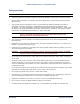
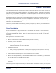
Tsunami Multipoint Version 1.3 Installation Guide 4.45 to obtain newtons, or by 0.45 to obtain kilograms of force. Similarly, foot-pounds can be multiplied by 1.36 to obtain Newton-meters, or by 0.138 to obtain kgm-meters. Note: For definitions of wind loading specifications for antennas and towers, refer to TIA/EIA-195 (for antennas) or TIA/EIA-222 (for towers) specifications. Figure 1. BSU Wind Loading Analysis Figure 2. SU Wind Loading Analysis Chapter 1.
Tsunami Multipoint Version 1.3 Installation Guide Lightning You should always consider the potential for lightning damage to radio equipment when planning a wireless link. A variety of lightning-protection and grounding devices are available for use on buildings, towers, antennas, cables, and equipment that could be damaged by a lightning strike, whether located inside or outside the site.
Tsunami Multipoint Version 1.3 Installation Guide Co-Channel and Adjacent Channel Interference Co-channel interference results when another RF link is using the same channel frequency. Adjacentchannel interference results when another RF link is using an adjacent channel frequency. In selecting a site, a spectrum analyzer can be used to determine whether any strong signals are present and, if present, determine how close they are to the desired frequency.
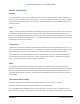
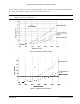
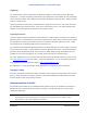
Tsunami Multipoint Version 1.3 Installation Guide BSU Antenna Characteristics Polarization: LHCP (Left-Hand Circular Polarization) Azimuth Beamwidth: 60-degree Elevation Beamwidth: 6-degree Figure 3. BSU Azimuth Antenna Pattern Figure 4. BSU Elevation Antenna Pattern Chapter 1.
Tsunami Multipoint Version 1.3 Installation Guide SU Antenna Characteristics Polarization: LHCP Beamwidth (Azimuth/Elevation): 10-degree Figure 5. SU Antenna Pattern Even when other licensees are not an issue, if you are using a network deployment using the “cell” approach, all these considerations are still important for reducing interference between your own adjacent installations. Antennas are tuned to operate on a specific group of frequencies.
Tsunami Multipoint Version 1.3 Installation Guide Path Planning To get the most value from a wireless system, path planning is essential. In addition to the fact that radio signals dissipate as they travel, many other factors operate on a microwave signal as it moves through space. All of these must be taken into account, because any obstructions in the path can attenuate the signal.
Tsunami Multipoint Version 1.3 Installation Guide Channel/Frequency Plans Tsunami Multipoint offers several frequency plans to provide a means for overcoming interference. If one part of the 5.8 GHz spectrum is occupied when you deploy the product, you can select a different frequency plan to bypass the interfering frequency. Plan 4 is the default. Operating frequencies in the 5 and 6 plans overlap. See “Change the Frequency Plan and Operating Frequency” on page 50 for more information.
Tsunami Multipoint Version 1.3 Installation Guide Chapter 2. Deploying the Base Station Unit (BSU) This chapter describes how to mount and deploy the Base Station Unit including the GPS Antenna (required when you install multiple BSUs at the same location). Unpacking the System The product’s shipping boxes should be left intact and sheltered until arrival at the installation site. If the shipping container shows signs of damage, immediately notify the transportation company.
Tsunami Multipoint Version 1.3 Installation Guide Proxim recommends that you retain all the packaging materials (including all internal boxes). In the unlikely event that the equipment must be returned to the factory, use the original packing materials for return shipment. The packaging materials are also recommended for transporting the equipment from location to location.
Tsunami Multipoint Version 1.3 Installation Guide Figure 7. BSU Mounting Hardware Required Tools: 9/16” (14-23 mm) wrench 6” (155 mm) crescent wrench Note: Torque all #3/8 bolts and nuts 250 ± 10 in-lbs. BSU Mounting: Ground Work To assemble the BSU’s mounting components: 1. Place the BSU face (transmitter side) down on a flat surface. 2.
Tsunami Multipoint Version 1.3 Installation Guide 4. Connect the downtilt bracket to the notched bracket using two 3/8-16x1 1/4 hex head screws, #3/8 split lock washers, #3/8 (star) lock washers, and 3/8-16 hex nuts (see Figure 9). Figure 9. Downtilt and Clamp Brackets with Screws Attached Figure 10. Bracket Assembly Detail of Screw, Washers, and Nut 5.