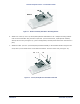
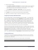
Tsunami Multipoint Version 1.3 Installation Guide Figure 11. Bracket Assembly Attached to Mounting Bracket 6. Attach one of the 1/2-13x7 1/2 screws/clamp bracket assemblies to the u-shaped mounting bracket near the end of the BSU using two sets of 3/8-16x1 1/4 hex head screws, #3/8 split lock washers, and 3/8-16 hex nuts (see Figure 12). (In this configuration, the BSU points down when mounted on a pole.) 7.
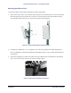
Tsunami Multipoint Version 1.3 Installation Guide Mounting the BSU to a Pole To mount the BSU to a pole using the attached mounting components: 1. Lash the unit to the pole or use a hoisting rope to keep the unit in place while you mount it. Slide the two strap clamps over the two sets of 1/2-13x7 1/2 screws and secure the strap clamps using four #1/2 split lock washers and four 1/2-13 hex nuts (see the following photo). Figure 13. Strap Clamps Attached and Mounted BSU 2.
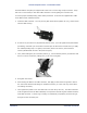
Tsunami Multipoint Version 1.3 Installation Guide The Base Station Unit (BSU) is shipped with a dust cover over the large 18-pin connector. Keep this cover on until ready to mate with cable connector to avoid getting the connector wet. To ensure proper weatherproofing, follow these procedures to connect the supplied Cat 5 cable to the BSU’s Power and Ethernet port. A. Check the BSU connector. The only moving part should be the plastic nut (“B”), which screws onto the BSU housing. B.
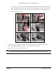
Tsunami Multipoint Version 1.3 Installation Guide Once mated, over-wrap the connectors (as demonstrated in the following table) with stretchy black self amalgamating tape (such as CTB-15 CATV TAPE-X5-BK-UN part #22150000 from DSG – CANUSA 173, Commerce Boulevard, Loveland, Ohio 45140, Tel. 1-800-422-6872) to ensure a better water seal. 4. 1) 2) 3) 4) 5) 6) Connect the other end of the Cat 5 cable to the BSU’s power supply. (The BSU’s power supply is ordered and shipped separately.
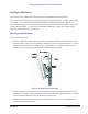
Tsunami Multipoint Version 1.3 Installation Guide Installing the GPS Antenna If you do not plan to install multiple BSU in the same geographical area skip this section If you plan to install multiple BSUs in the same geographical area (for example, one BSU might interfere with another), you must install the supplied GPS antenna (a small metal plate with a black 2"x 2" antenna and thin cable) on each BSU. Each BSU uses a global positioning system (GPS) to synchronize its clock with other BSUs.
Tsunami Multipoint Version 1.3 Installation Guide 4. Remove the water-protection cap from the top of the BSU and screw on the cable from the GPS antenna to the connector on the top of the BSU. Installing BSU Configuration Software The next step is to configure the BSU. The BSU is configured from a PC running the BSU Configuration Software (Versions 1.4 or 1.5). This PC communicates with the BSU through its Ethernet port.
Tsunami Multipoint Version 1.3 Installation Guide ▪ Install the BSU first before installing any SUs. ▪ Once a link has been established, check the RSL at the SU, and if too high, miss-point the antenna slightly to reduce the receive power. Configuring the Base Station Keep in mind the following when configuring a BSU: ▪ The configuration commands are NOT case-sensitive.
Tsunami Multipoint Version 1.3 Installation Guide 3. Configure the BSU’s IP settings: Type setIP and press Enter, where is the new IP address you want to assign to the unit. For example, type setIP 192.168.20.20 to assign this IP address to the BSU. A. Close the Base Station Configuration Software and change the IP address of the computer’s Ethernet card so that it is in the same IP network as the BSU’s new IP address; restart the computer if necessary. B.
Tsunami Multipoint Version 1.3 Installation Guide 8. Set the desired frequency plan using the frequency command. (frequency < a | b | c | d | e| f >; with e being available for the 5 and 6 channel plans and f being available for the 6 channel plans only. 9. Set the BSU’s desired transmit power level using the txPowerLevel command. Note: Typically the power level is set to 17 dBm in the field (maximum setting) and 6 dBm for indoor range testing (minimum level). 10.
Tsunami Multipoint Version 1.3 Installation Guide 3. Configure the SU’s IP settings: º Enter setSUIP to set the SU’s IP address. Proxim suggests that you configure each SU with a unique IP address in the same IP subnet as the BSU in Bridging mode and configure each SU with a specific subnet in IP routing mode. º Enter setSUSubnet to set the SU’s subnet mask. 4.
Tsunami Multipoint Version 1.3 Installation Guide Follow these steps to run the test: 1. Open the Base Station Configuration Software. 2. Enter BSUlog 1 1. 3. The second output column is GPS sync, which will read –1 until the GPS can acquire the requisite number of satellites. When this number reads 0, GPS has acquired at least one satellite; when it reads 4, at least four satellites have been acquired and GPS is functional. 4. Enter BSUlog 0 to turn off BSU log. 5.
Tsunami Multipoint Version 1.3 Installation Guide Chapter 3. Deploying the Subscriber Unit Mounting the Subscriber Unit (SU) The outdoor component of the Subscriber Unit (SU) is designed to directly mount to a pole. Using the supplied U-bolts, you can mount the SU to a 1-1/4 inch to 1-3/4 inch pole (outside diameter). Using optional mounting brackets, you can mount the SU to a wall or other flat surface. Figure 16.
Tsunami Multipoint Version 1.3 Installation Guide Note: The following instructions assume that you will slide the SU’s mounting bracket/pole assembly onto a pole. If this is not practical (for example, the pole is too tall or its top and bottom are permanently mounted to structures), follow the steps below, but assemble the mounting bracket/pole assembly around the pole. 1. Insert the two U-bolts into the mounting clamp housing and attach the two #5/16 nuts and 5/16 flat washers. 2.
Tsunami Multipoint Version 1.3 Installation Guide 4. Insert the two #10-32 screws in the sides of the mounting clamp housing/pole clamp assembly and loosely attach the two #10-32 nuts. Figure 19. Mounted SU 5. After you aim the SU (see “Aiming the SU” on page 35), tighten the two #10-32 screws and nuts to secure the SU in position. 6. Insert the O-ring into the SU’s Power and Ethernet port. 7.
Tsunami Multipoint Version 1.3 Installation Guide 8. Connect the other end of the Cat 5 cable to the SU’s power supply. Be sure the Tsunami Multipoint Subscriber Unit connector is properly “contacted” or the unit may fail; you should hear a “click” when installing the cable connector to its chassis. The proper way to install is as follows: A) Insert the O-ring into the SU’s Power and Ethernet port. B) Loosen the rear nut on the end of connector cable.
Tsunami Multipoint Version 1.3 Installation Guide 6. Follow the on-screen instructions to install the software. 7. Click Done when the installation is finished to close the installer. Aiming the SU 1. Launch the Subscriber Utility. Figure 21. Settings Page in Subscriber Utility 2. Choose the desired frequency plan and operating frequency. The factory default is the 4 channel frequency plan and frequency auto (the SU looks through all frequencies).
Tsunami Multipoint Version 1.3 Installation Guide 4. Click Save Settings and Install Subscriber Unit to launch the aiming tool. Figure 22. Aiming Tool in Subscriber Utility 5. Slowly adjust the position of the SU until you have maximized the strength of the radio signal. º The SU beeps after it has detected a signal from the BSU. The beeps increase in frequency as the strength of the signal received from the BSU increases.
Tsunami Multipoint Version 1.3 Installation Guide Figure 23. Subscriber Utility Status Window Base Station ID Displays the Terminal ID assigned to the BSU with which the SU communicates.
Tsunami Multipoint Version 1.3 Installation Guide Frequency Channel Shows the current channel plan/frequency setting (for example, 4C). See “Change the Frequency Plan and Operating Frequency” on page 50 for information. By default, the SU is set to automatically search for the correct frequency channel. Receive Signal Quality (dBm) Shows the quality of signal received by the local SU (in dBm). This value represents the estimated received signal level, plus an offset of 120 dB.
Tsunami Multipoint Version 1.3 Installation Guide If the ping tests are unsuccessful, attempt the following: ▪ Check all IP and computer configurations (for example, if you attempt to ping the BSU from the SU configuration computer and the BSU and SU’s are in separate networks you must have the configurations computers gateway set to the SU for the ping to work.) ▪ Adjust the network’s IP settings, if necessary, to achieve IP connectivity.