Tsunami Multipoint Version 1.3 Installation Guide Chapter 4. System Diagnostics and Operating Tips This section describes several diagnostic tests you can perform once the Tsunami MP equipment is installed. These tests assist you in determining whether the equipment is functioning as expected. In addition, we include some miscellaneous useful information for deploying a Multipoint network. Radio Diagnostics Use the diagnostic tools described in this section to determine if your wireless link is stable.
Tsunami Multipoint Version 1.3 Installation Guide Monitor the Es/No ratio (Es/No reports the energy per symbol-to-noise spectral density ratio (in dB)). Low Es/N0 or varying Es/N0 can indicate path or interference problems.
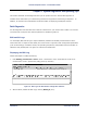
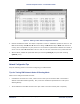
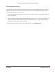
Tsunami Multipoint Version 1.3 Installation Guide 2. When finished, disable the SU log by entering SUlog1 0 (zero) or SUlog2 0 (zero) (depending upon which log you displayed). SUlog1 provides the following information: SU ID The Terminal ID of the monitored SU. RSL Shows the shows the RSL (receiver signal level) at the output of the antenna (in dBm). TX Power Shows the SU’s TX power at the input to the antenna (in dBm).
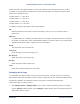
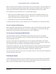
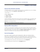
Tsunami Multipoint Version 1.3 Installation Guide IB pkts Shows the number of inbound packets transmitted. OB pkts Shows the number of outbound packets received. OB PE Shows the number of outbound packet errors. OB PER Shows the error rate for outbound packets received. Time Shows the cumulative polling time (in seconds). Figure 26. SU Log 2 Uplink BER Test The Uplink BER Test determines the BER (bit error rate) of the uplink signal.
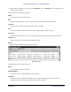
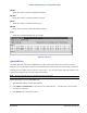
Tsunami Multipoint Version 1.3 Installation Guide Figure 27. BER Log in Base Station Configuration Software 4. Monitor the BER test results. The Es/No is reported in column 1 and BER is reported in column 2. The BER should initially read 0E-6 or oE-7 but then change to 0E-8 and finally to 0E-9 while the test is running. This corresponds to 0 (zero) bit errors. The numbers in parentheses indicates the number of errors over the total.
Tsunami Multipoint Version 1.3 Installation Guide Make sure that an SU and its directly connected devices are in the same subnet. The subnet address of a device can be obtained by performing a logical “AND” of the device’s IP address with its subnet mask. A subnet mask of 255.255.255.0 implies that there are 255 IP addresses within the same subnet.
Tsunami Multipoint Version 1.3 Installation Guide Password Protection Tsunami Multipoint provides two levels of password protection: ▪ user level – lets the user display the system’s current status only. ▪ admin level – lets the user display the system’s status and change its configuration. The default password is “null.” Password protection for either password level (user or admin) can be turned on and off. By default, password protection is turned off.
Tsunami Multipoint Version 1.3 Installation Guide Turning Off Password Protection To turn off password protection, from the BSU console, enter setpw where: = either admin or user, depending upon which level of password protection you want to remove. For example, if the current admin password is “superuser,” to remove the admin password, enter setpw admin superuser null null. = the old password.
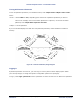
Tsunami Multipoint Version 1.3 Installation Guide Activating Range Security The Range Security option helps prevent unauthorized SUs from communicating with a BSU. When the Range Security option is on, if an SU attempts to enter the network, the BSU checks the range value reported by the SU. This works as follows: ▪ The first time the SU tries to enter the network, the SU’s range is stored in the BSU’s flash memory for future reference.
Tsunami Multipoint Version 1.3 Installation Guide Appendix A. Initial Settings Specify the Desired Modulation (Data Rate) To configure the BSU to use the modulation setting required by your application (20, 30, 40, or 60 Mbps), from the BSU console, enter modulation , where: = 0 (zero) = QAM16 (60 Mbps) 1 = QAM8 (40 Mbps) 2 = QPSK3Q (30 Mbps) 3 = QPSK1H (20 Mbps) The BSU automatically restarts and then comes up with the new modulation setting.
Tsunami Multipoint Version 1.3 Installation Guide Change the Frequency Plan and Operating Frequency Tsunami Multipoint offers several frequency plans and operating frequencies to provide a means for overcoming interference. If one part of the 5.8 GHz spectrum is occupied when you deploy the product, you can select a different frequency plan to bypass the interfering frequency.
Tsunami Multipoint Version 1.3 Installation Guide Appendix B. Installing the Configuration Software and Upgrading Firmware Four major pieces of software are required to install the SU and BSU: ▪ ▪ ▪ ▪ Tsunami Multipoint Base Station Configuration Software Console, Version 1.5 (BSU 1.5 Console) Tsunami Subscriber Utility BSU Firmware Version 1.3 SU Firmware Version 1.3 If the BSU and SU are new from the factory they will be preloaded with BSU Firmware Version 1.3 and SU Firmware Version 1.
Tsunami Multipoint Version 1.3 Installation Guide Installing the Base Station Configuration Software Version 1.5 Console To install the BSU/SU 1.5 Console: 1. From the Windows Explorer Console1.5 directory, double-click on the BSU folder. 2. Double-click on the Install icon. Two windows open simultaneously: InstallAnywhere Web Installer — Microsoft Internet Explorer (in disabled mode) superimposed by Security Warning (in enabled mode).
Tsunami Multipoint Version 1.3 Installation Guide After the download completes, double-click on BS.exe to begin installation. When the Tsunami Multipoint Base Station Configuration Software Introduction window is displayed; click Next. 4. Click Next on the Important Information window once you have completed reading the text. When the License Agreement window is displayed, accept the terms of the License Agreement and click Next to proceed with the installation. 5. 6.
Tsunami Multipoint Version 1.3 Installation Guide Subscriber Utility Software System Requirements Same as for Base Station Configuration Software (see “System Requirements” for the BSU on page 51). Installing the Subscriber Utility Software System requirements for the Subscriber Utility software are the same as for the Base Station Configuration software., To install the utility software: 1. Identify the computer on which you plan to run the Subscriber Utility. Note: 2.
Tsunami Multipoint Version 1.3 Installation Guide Remote Over-the-Air Download to SUs You can upgrade your SUs to Version 1.3 from the Base Station Configuration Software Console of the BSU. Normally, all SUs in the network are upgraded at the same time. However, if one or more SUs fail to receive the download code correctly, the upgrade is aborted and a second attempt must be made. SUs that have been upgraded successfully ignore reprogramming of the same codes. To download remotely to SUs: 1.
Tsunami Multipoint Version 1.3 Installation Guide To download locally to an SU: 1. From the SU 1.4 or 1.5 Console, select the Download menu. 2. Select Local Firmware. 3. From the Look In search field, choose the binary file to be downloaded (PMP_SU_release1-3.mot) from the appropriate directory and click Select. The download requires about 2 minutes. Once the download is complete, the banner indicating Version 1.3 is displayed.
Tsunami Multipoint Version 1.3 Installation Guide Appendix C. Technical Specifications The following technical specification is for reference purposes only. Actual product performance and compliance with local telecommunications regulations can vary from country to country. Proxim Corporation only ships products that are type approved in the destination country.
Tsunami Multipoint Version 1.3 Installation Guide Tx Power BSU .....................+6 to +17 dBm (into antenna port) SU .......................-48 to +15 dBm (into antenna port) Antenna BSU .....................Integrated, LHCP (left-hand circular polarization) 18 dBi SU .......................
Tsunami Multipoint Version 1.3 Installation Guide System Operating Frequency Range............................ 5725-5825 MHz Radio Access Method ..................................... TDMA Duplexing .................................................... Time Division Duplex (TDD) Integrated Antenna (BSU).............................. 19 dBi (60° Azimuth. X 6° Elevation) LHCP Integrated Antenna (SU)................................ 20 dBi (10° Azimuth. X 10° Elevation) LHCP Max Subscriber Units/BSU.............
Tsunami Multipoint Version 1.3 Installation Guide Power/Environment Safety Electrical Base Station Unit .......................................... -36 to –60 Volts DC, 1.25 Amps Base Station Unit Power Brick ......................... 100-240 Volts AC Base Station Unit Power Block ........................ 48 Volts DC Subscriber Unit............................................. 18 to 28 Volts DC, 0.8 Amps Subscriber Unit Power Brick............................
Tsunami Multipoint Version 1.3 Installation Guide Subscriber Unit (Outdoor Unit) Size (WxHxD) .............................................. 10.5 x 10.5 x 6.8 inches/26.5 x 26.5 x 17.4 cm Weight ........................................................ 10 lbs/4.5 kg Subscriber Unit Power Brick (Indoor Unit) Size (SxHxD) ............................................... 36 x 5.1 x 2.6 inch/92 x 130 x 67 cm Weight ........................................................ 2.7 lbs/1.
Tsunami Multipoint Version 1.3 Installation Guide Appendix D. Constructing Power and Ethernet Cables Subscriber Unit Power and Ethernet Cable Perform the following steps to construct a Subscriber Unit power and Ethernet cable of the desired length. CAUTION For best results this cable should be constructed by professional cable manufacturer or by experienced personnel with proper tools. Contact Proxim Customer Service or Sales for recommendations for a manufacturer near your vicinity. Figure 30.
Tsunami Multipoint Version 1.3 Installation Guide Assembling the 8-Pin DIN Connector To assemble the 8-pin DIN connector: 1. Slide the jacket of the 8-pin DIN connector over one end of the Cat 5 UV cable. 2. Prepare the Cat 5 cable ends by removing 0.75” of the main jacket. Do not cut the twisted pair wires. 3. Remove 0.06” of insulation from the end of each wire in each twisted pair. 4. Solder each wire prepared in step 3 to the appropriate cup on the DIN connector.
Tsunami Multipoint Version 1.3 Installation Guide 6. Using small pliers, crimp the metal strain relief over the Cat 5 cable. Do not cut into the cable. Slide the jacket over the completed assembly. Figure 33. Jacket Placed Over 8-Pin DIN Connector Assembling the RJ45 (Woodhead) Weatherproof Connector CAUTION For best results this cable should be constructed by professional cable manufacturer or by experienced personnel with proper tools.
Tsunami Multipoint Version 1.3 Installation Guide 7. Slide the threaded Woodhead cover over the completed assembly and loosely tighten it down to the cable. Figure 36. Woodhead Cover Placed Over RJ45 Connector 8.
Tsunami Multipoint Version 1.3 Installation Guide 1. Cut 750-00891-00 tubing or Proxim approved equivalent to 1.25" +/- 0.1". 2. Using silicone spray or equivalent lubricant, spray the end of the wire, then slide the tubing onto the wire, approximately 4" out of the way. 3. Slide the backshell with the ½" (inside diameter) rubber cable seal onto the wire. 4. Crimp the connector pins onto the individual wires using a Positronic crimping tool 9507 (crimping frame) and 9502-20 (die). 5. Insert the 1.
Tsunami Multipoint Version 1.3 Installation Guide About Crimping Loose piece contacts are designed to be crimped with crimp tooling (hand tools, die assemblies, or crimping heads), but can be done with normal hand tools. The applicable crimp tooling for the contacts is described later in this section. Read the documentation included with the crimp tooling for the proper crimping procedure. Figure 40. Crimping Styles and Insertion Figure 41. Indoor Portion of Power and Ethernet Cable Appendix D.
Tsunami Multipoint Version 1.3 Installation Guide Wire Size and Preparation Contacts are available for the wire sizes specified. Prepare the wire for crimping by stripping the insulation. DO NOT nick, scrape, or cut the stranded or solid wire conductor while stripping the insulation. Note: When using twisted pair cable, cut one wire shorter than the other. Figure 42. Wire Preparation Tooling AMP hand crimping tools and applicators are available for applying crimp type contacts.
Tsunami Multipoint Version 1.3 Installation Guide Installing the AMP CPC Connector with Shield and Strain Relief The indoor end of the BSU Power and Ethernet cable uses an 8-pin circular plastic AMP connector with crimp contacts. The connector is a reverse sex plug with male connector pins. The plug provided is not weather tight and is meant for indoor use only.
Tsunami Multipoint Version 1.3 Installation Guide Appendix E. Lightning Protection Recommendations This appendix describes Proxim Lightning Protection Recommendations for: ▪ Tsunami Multipoint Base Station Unit 40400-25/-65 ▪ Tsunami Multipoint Subscriber Unit 40100-251/-252/-651/-652 Introduction What is Lightning Protection? All outdoor electronic equipment is susceptible to lightning damage. Proper grounding to national and local codes is instrumental in providing human safety.
Tsunami Multipoint Version 1.3 Installation Guide Recommendation Proxim recommends the following for its Tsunami Multipoint products: Installation Requirement Proxim Product Industrial Commercial SOHO Tsunami Multipoint Base Station Unit (BSU) 20/60 Mbps Models (1) (1) (1) or (2) (up to 50 meters) Tsunami Multipoint Subscriber Unit (SU) 20/40/60 Mbps Models (1) (1) or (2) (up to 50 meters) (1) or (2) (up to 50 meters) (1) PolyPhaser 101-1218W-A.
Tsunami Multipoint Version 1.3 Installation Guide Transtector Systems Surge Supressor This outdoor-use, molded plastic, weather-tight enclosure is a surge suppressor designed to protect the Tsunami Multipoint SU and the QuickBridge unit from lightning damage. This product can be used for CAT5 cable lengths up to 50 meters from the outdoor Tsunami unit to indoor power adapter. The 1101-TSU uses silicon avalanche suppression diodes (SASD) to provide lower voltage protection level (VPL).
Tsunami Multipoint Version 1.3 Installation Guide Where Should the Protection Units be Located? At least one unit should be installed near every outdoor Tsunami unit. General guidelines are: ▪ Locate protection unit as close to the outdoor Tsunami unit as possible, where the lightning protection unit can be securely mounted to a flat surface and grounded properly. Ideally, this should be no further than five feet away from the outdoor unit.
Tsunami Multipoint Version 1.3 Installation Guide Pinout and Wiring Specifications: Note: Surge Side Equipment Side Application Wire Color Vdc in VDC out 48Vdc White/Orange RTN in RTN out Ground Orange Vdc in VDC out 48Vdc White/Brown RTN in RTN out Ground Brown Tx+ in Tx+ out Tx + Green Tx- in Tx- out Tx - White/Green Rx+ in Rx+ out Rx + Violet Rx- in Rx- out Rx - White/Violet GND GND Shield, if req.
Tsunami Multipoint Version 1.3 Installation Guide Pinout and Wiring Specifications: Surge Side Equipment Side Application Wire Color VDC in RTN in VDC in RTN in Tx+ in Tx- in Rx+ in Rx- in GND VDC out RTN out VDC out RTN out Tx+ out Tx- out Rx+ out Rx- out GND 48 VDC Ground 48 VDC Ground Tx + Tx Rx + Rx Shield, if req. White/Orange Orange White/Brown Brown Green White/Green Violet White/Violet N/A For additional information, go to www.transtector.com.
Tsunami Multipoint Version 1.3 Installation Guide Appendix F. Technical Support and Training If you are having a problem using a Tsunami Multipoint and cannot resolve it with the information in “Appendix A. Troubleshooting” in the Tsunami Multipoint Version 1.