Lynx.
Lynx.GX and Tsunami Radio Installation and Configuration Notices Copyright and Service Marks Copyright © 2002 by Proxim. All rights reserved. No part of this book may be reproduced without prior written permission from Proxim. The information contained in this book is subject to change without notice. Proxim shall not be liable for errors contained herein or for incidental or consequential damages in connection with the furnishing, performance, or use of this book or equipment supplied with this book.
Lynx.GX and Tsunami Wireless Radio Installation and Maintenance This device complies with Part 15 of FCC rules and RSS-210 of Industry Canada. Operation is subject to the following two conditions: (1) this device may not cause interference, and (2) this device must accept any interference, including interference that may cause undesired operation of the device. This device must be installed professionally.
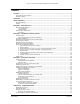
Lynx.GX and Tsunami Radio Installation and Configuration Contents NOTICES ......................................................................................................................................... 2 Copyright and Service Marks ..........................................................................................................2 Regulatory Notice .........................................................................................................................2 CONTENTS............
Lynx.GX and Tsunami Wireless Radio Installation and Maintenance Short Paths.......................................................................................................................... 51 Narrow Beam Antennas (High Gain)........................................................................................ 52 Frequency Selection.............................................................................................................. 52 Antenna Polarization ................................
Lynx.GX and Tsunami Wireless Radio Installation and Maintenance Figure Figure Figure Figure Figure 13 14 15 16 17 Contents CPN 62140 DS-3 Digital Radio Connections ........................................................................................... 16xT1 Digital Radio Connections .......................................................................................... 21xE1 and 28xT1 Connections.............................................................................................
Lynx.GX and Tsunami Radio Installation and Configuration About This Book This book provides the information needed to install, maintain, and troubleshoot the Lynx.GX and Tsunami (GX platform) Radios. Be sure to read “Product Safety Instructions” in Chapter 1 before installing this product. This device must be professionally installed. Instructions for setting the transmitter RF output power are referenced in “Output Power Adjustment.
Lynx.GX and Tsunami Radio Installation and Configuration Chapter 1. Introduction Proxim Corporation introduces the GX platform of wireless bridge products - Lynx.GX wireless radios and the Tsunami wireless bridges. The split-box design lets you install both units indoors, or one unit indoors (the IDU, or indoor unit) and one unit outdoors (the RFU, or RF Unit). The units can be mounted in a 19-inch rack; each piece is 1.75” high, occupying one rack unit (RU).
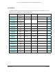
Lynx.GX and Tsunami Wireless Radio Installation and Maintenance Lynx.GX Models The following tables list the Lynx.GX models as well as some of their basic specifications. For full specifications, see “Appendix C: Product Specifications.” Model Number Manufacturing Part Number 51145-10L0 51145-10H0 62139 62142 8 T1 ports 5.8 GHz ISM 51145-20L0 51145-20H0 62144 62145 8 E1 ports 5.8 GHz ISM 51155-20L0 51155-20H0 62148 62149 51850-10L0 51850-10H0 TBD TBD 4 T1 ports 5.
Lynx.GX and Tsunami Wireless Radio Installation and Maintenance Basic Specifications for Lynx.GX models Bandwidth (MHz) Typical Output Power 8 T1 125 8 E1 100 or 125 ≥20 dBm 4 T1/E1 Chnl Plans Main Interface Connectors Aggreg. Capacity (Mbsp) Line Code/ Channel DSX-1 [RJ48c] 13.5 AMI/B8ZS 18 18 2 125 3 DSX-1 [RJ48c]; CEPT-1 [RJ48c or 2xBNC] DS-3 9 27 16 T1 12 E1 100 ≥17 dBm 28 T1 Line Buildout/ channel 1 DSX-1 and CEPT-1: using 64 pin DSX connector AMI/B8ZS; HDB3 0–600 ft.
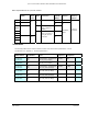
Lynx.GX and Tsunami Wireless Radio Installation and Maintenance Basic Specifications for Tsunami models Bandwidth (MHz) Typical Output Power Chnl Plans Main Interface Connectors Aggreg. Capacity (Mbsp) Line Code / Channel Line Buildout/ channel 0–655 ft.
Lynx.GX and Tsunami Wireless Radio Installation and Maintenance This product must be serviced by trained personnel only. Do not: • Disassemble this product. By opening or removing any covers, you could expose yourself to hazardous energy parts. Incorrect reassembly of this product can cause a malfunction or electrical shock when the unit subsequently is used. ■ Insert any objects of any shape or size inside this product while powered.
Lynx.GX and Tsunami Wireless Radio Installation and Maintenance Figure 1 Proper Equipment Earthing/Grounding Grounding Be sure to: ■ Use a common ground for everything ■ Ground the radio to the rack Be careful with DC power grounding: ■ Grounding DC supply may create ground loops ■ If DC source is referenced to ground, use DC power and jumper to ground ■ Best if DC source “floats” in case of lightning or other surge Other grounding: ■ Mast ■ Transmission line Chapter 1.
Lynx.GX and Tsunami Radio Installation and Configuration Chapter 2. Planning for Installation There are several planning factors to be considered prior to installing the Tsunami or Lynx radio system.
Lynx.GX and Tsunami Wireless Radio Installation and Maintenance To maximize link availability, calculate 0.6 times the first Fresnel zone and add this value to path clearance based upon the primary path (in addition to earth curvature, trees, buildings, and so on). The radios will not perform properly unless they have line-of-sight and proper path clearance between their corresponding antennas.
Lynx.GX and Tsunami Wireless Radio Installation and Maintenance Lp is the Path loss, defined by: Lp (dB) = 96.6 + 20 log10F + 20 log10D where: F is the Frequency of the radio system in GHz (5.8 in the case of this model) D is the Distance of the path in miles The results of this link budget calculation are very important for determining any potential problems during installation.
Lynx.GX and Tsunami Wireless Radio Installation and Maintenance As a rule of thumb, do not place opposite frequency plan radios (such as A1 and A2) at the same site. In most cases, you should use the same frequency plan (such as A1 and A1) or, in some cases, a different frequency plan from the same side of the band (such as A1 and B1, when more than one channel plan is available). With careful engineering, you can easily place more than one radio of the same frequency channel plan at the same site.
Lynx.GX and Tsunami Wireless Radio Installation and Maintenance Planning for Antenna Installation In general, the larger the antenna used with the radio, the better the link performs. Larger antennas have narrower beamwidth and higher gain, which yield better link performance (higher fade margin, better availability) and improve immunity to interference (due to the narrower beamwidths).
Lynx.GX and Tsunami Wireless Radio Installation and Maintenance 6-foot parabolic Gabriel Gabriel Radio Waves Andrew RFS RFS SSP6-52A HSSP6-52 SP6-5.2 P6F-52 SPF6-52A SDF6-52A 37.5 37.2 37.7 37.6 37.4 37.4 8-foot parabolic Gabriel Gabriel SSP8-52A HSSP8-52 39.8 39.6 Transmission Line Type Manufacturer Model Number Loss/100 (dB) ft. Notes ½-inch foam coax Andrew LDF 4-50 6.1 Add –0.25 dB per connector 5 Andrew LDF 4.5-50 4.7 Add –0.25 dB per connector Waveguide Andrew EW-52 1.
Lynx.GX and Tsunami Wireless Radio Installation and Maintenance Reviewing the Installation Process The following is an overview of the installation process to assist you in your planning activities. 1. Test radios back-to-back and configure ■ Use a minimum of 60 dB and no more than 80 dB attenuation and a short low-loss RF transmission line to connect the two radios. ■ Apply power. ■ Verify the RF Link LED is not red.
Lynx.GX and Tsunami Wireless Radio Installation and Maintenance 5. Align antennas ■ Rough align antenna azimuth and elevation based upon path planning (using compass bearing or milestone sighting, telescopic sight, binoculars, and so on). ■ Use a Digital Volt Meter (DVM) or headphones/earpiece/speaker to read the radio’s RSL voltage provided on the RFU to peak antennas. º If the RFU is mounted indoors, you may need to temporarily run separate wires from the RSL port to antenna.
Lynx.GX and Tsunami Wireless Radio Installation and Maintenance 7. Troubleshooting ■ Most common problems are poor transmission line connector terminations. º Best way to test is a return loss measurement (VSWR). º Basic function can be tested using a continuity and short test with DVM. º The transmission line can be evaluated with a spectrum analyzer connected to the radio through the cable and comparing when spectrum analyzer is connected directly to the radio without the cable.
Lynx.GX and Tsunami Radio Installation and Configuration Chapter 3. Installing the Units Mounting the Units Assembling Required Materials The radios are shipped in boxes unless ordered as an integrated system and configured at the factory. In that case, the equipment may be racked and shipped in a crate. The equipment is packaged so as to prevent damage in transit.
Lynx.GX and Tsunami Radio Installation and Configuration If the shipping container shows signs of damage, notify the transportation company immediately. Upon receipt, inspect contents to make sure no parts are missing or damaged. You should retain all the packaging materials (including all internal boxes). In the unlikely event that you must return the equipment to the factory, use the original packing materials for return shipment.
Lynx.
Lynx.GX and Tsunami Wireless Radio Installation and Maintenance Installing the Indoor Unit Rack mounting of the IDU is the ideal configuration. The Lynx and Tsunami radio alternatively can be placed on a tabletop or a cabinet shelf. You should secure the radio system with a strap when not mounted directly to a racking system. For rack mounting, to avoid interference with the RF unit or antenna cables, you should mount the unit at the highest space in a standard 19-inch rack.
Lynx.GX and Tsunami Wireless Radio Installation and Maintenance 3. Position the radio in the rack and align the holes in the mounting bracket with the holes in the rack. If you are installing the IDU in a 23-inch rack, you must attach extenders to the rack mounting brackets, as shown in the following figure: Chapter 3.
Lynx.GX and Tsunami Wireless Radio Installation and Maintenance 4. Insert two bolts and lock washers, appropriate for your 19-inch rack, into each of the mounting brackets and tighten. Important: When the RFU is rack mounted, it must be mounted directly above the IDU and facing with the connectors forward in the same direction as the front panel of the IDU (as shown). The IDU fan exhaust is used to cool the RFU in a rack mount configuration.
Lynx.GX and Tsunami Wireless Radio Installation and Maintenance 2. Wrap band clamp around pole/mast and through the vertical slots near the top of the mounting plate. Repeat for lower slots. 3. Tighten both band clamps sufficiently to prevent the mounting plate from rotating on the pole/mast; you are now ready to mount the RF unit onto the bracket assembly. 4.
Lynx.GX and Tsunami Wireless Radio Installation and Maintenance Installing and Adjusting the Antenna The installation information discussed in this section is generic. For installation procedures specific to the antenna you are installing, refer to the antenna manufacturer’s documentation. Antenna Installation WARNING (FCC requirement for implementation in the USA): Antennas used for the transmitter must be fix-mounted on outdoor permanent structures with a separation distance of at least 1.
Lynx.GX and Tsunami Wireless Radio Installation and Maintenance Alignment Guidelines When aligning antennas, if the RFU is located indoors or distant from the antenna location, you may want to run wires or a cable from the RSL test point to the antenna so that the voltmeter reading or audio device is directly visible and audible to the technicians aligning the antenna. Alternatively, you can use coaxial couplers to couple the RSL voltage from an IDU to bring the voltage to the antenna location.
Lynx.GX and Tsunami Wireless Radio Installation and Maintenance Note: Use the instructions provided by the antenna manufacturer to verify that both antennas are on the same polarization; otherwise, the RSL will be approximately 25 to 30 dB below the calculated level. Because maximizing the receive RF signal level at each end of the radio link is critical, most antennas also require fine alignment using an operating link.
Lynx.GX and Tsunami Wireless Radio Installation and Maintenance Above -30 dBm RSL, the receiver can produce errors; however this level is rarely exceeded. Refer to Calculating Received Signal Level and Link Budget to calculate the anticipated RSL. During anomalous propagation conditions, the RSL can fade up but does not typically increase by more than 10 dB (except in unusual, very long paths, which may increase by 15 dB).
Lynx.GX and Tsunami Wireless Radio Installation and Maintenance Antenna Cabling Guidelines for 5.8 GHz Units ■ Coaxial cables of 7/8-inch or larger diameter can exhibit moding at 5.8 GHz and are never recommended. Also, some small diameter cable types, such as RG-8, will have high loss or poor VSWR at these frequencies. If small diameter cables are required, be certain to keep the lengths of these cables as short as possible. ■ For wave guide transmission line at 5.
Lynx.GX and Tsunami Wireless Radio Installation and Maintenance RF transmission line must never be bent, twisted, or deformed in any way. Pay close attention to the transmission line specifications for bend radius when installing. 3. Support the transmission line in a tray on horizontal runs and by hangers on vertical runs. Space hangers according to the manufacturer instructions (typically every five feet under conditions of no ice and not greater than 85 mph winds). 4.
Lynx.GX and Tsunami Wireless Radio Installation and Maintenance Power Connections The following sections describe the wiring and power connections for the Lynx radios. The Lynx radios do not have a power on/off switch. and is operational immediately. When you connect the DC power, the unit powers up There can be up to 200mW of RF power present at the antenna port.
Lynx.GX and Tsunami Wireless Radio Installation and Maintenance To wire the DC power, wire the power cable with an adequate current rating (minimum 18 AWG) into the terminal block using the screw connections on the terminal block. Figure 7 Power Connection for IDU The recommended minimum current rating of external fuses and cables is 5 amps. The Lynx radios consume less than 3.1 Amp ■ + 48V. If using negative power, connect the negative voltage to pin 1.
Lynx.GX and Tsunami Wireless Radio Installation and Maintenance CAUTION! Do not connect the DC power plug to the terminal until the RFU is connected to the IDU and the antenna, or appropriate termination. Do not connect the RFU-to-IDU cable while power is applied to the IDU. The IDU can be powered without the RFU connected; however, power should be removed before the RFU is connected and reapplied after the cable is connected and the RFU is properly terminated at the RF port.
Lynx.GX and Tsunami Wireless Radio Installation and Maintenance traffic over the link. This helps in getting the system running more rapidly. Assure that both antennas are set for the same polarization (vertical or horizontal at both ends). 2. Connect the transmission line to the antenna and feed it to the Lynx radio location. Connect the opposite end of the transmission line to the N-type female connector located on the RFU through a lightning arrestor.
Lynx.GX and Tsunami Wireless Radio Installation and Maintenance attenuation then can be added to the value of the RF power meter reading to obtain the actual transmitter output power. 7. Confirm Received Signal Level (RSL). Connect a voltmeter to the RSL measurement port on the RF Unit. This voltage reading corresponds to the Received Signal Level (RSL) of the near-end radio. RSL is the amount of signal the near-end radio is receiving from the far-end radio.
Lynx.GX and Tsunami Wireless Radio Installation and Maintenance 8. Verify the channel plans. Verify that the units follow the same channel plan and that the opposite Tx and Rx frequencies complete a matched pair of radios (for example, A1 and A2 make up a matched pair). 9. Connect the unit to the intended telecommunications equipment to pass the T1 traffic. Connect to the T1 circuits using 8-pin modular (RJ-48C) connectors. be off or green.
Lynx.GX and Tsunami Wireless Radio Installation and Maintenance Control Button and LED Descriptions Control Button Descriptions To RFU This is an RF TNC female connector that is an integral part of the system. The TNC connector is used to connect the IDU to the RF Unit. The voltage on this connector is 42 VDC. ± 24 VDC OR ±48 VDC The power receptacle recommendation for positive or negative DC power is 24 or 48. However, it will accept any voltage between 20 and 63 Volts.
Lynx.GX and Tsunami Wireless Radio Installation and Maintenance wireless link to the other. It can be used for separate data connections for serial devices. See “Appendix B. Connectors and Pin Assignments” on page 63 for AUX DATA port connector information. VF This RJ-45 connector is used to link two Lynx radios at a repeater site for Orderwire operation. This allows Orderwire calls to and from any point in the network.
Lynx.GX and Tsunami Wireless Radio Installation and Maintenance ORDERWIRE HANDSET This connection is used to access the electronic orderwire function (a facility for telephone style service from one radio to another). A standard analog telephone (with an electronic ringer) plugs into this connector.
Lynx.GX and Tsunami Wireless Radio Installation and Maintenance Port/Circuit Connections by Model The following connection types are illustrated in the figures that follow. 10/100 BaseT / 100 BaseFX The Tsunami Bridges use 100 Base-TX and 100 Base-FX RJ-48 modular port connectors and ST connectors for the Fast Ethernet interface. They carry the signals in and out of the radio. CHn T1 or E1 data channels. T1 A wayside data channel for T1 (DSX-1) interface voice connection.
Lynx.GX and Tsunami Wireless Radio Installation and Maintenance 12xE1 Radio Connections Figure 10 12xE1 Radio Connections 4xT1 and 4xE1 Connections Figure 11 4xT1 and 4xE1 Connections 8xT1 and 8xE1 Connections Figure 12 8xT1/8xE1 Digital Radio Connections DS-3 Digital Connections Figure 13 DS-3 Digital Radio Connections Chapter 3.
Lynx.GX and Tsunami Wireless Radio Installation and Maintenance 16xT1 Connections Figure 14 16xT1 Digital Radio Connections 21xE1 and 28xT1 Connections Figure 15 21xE1 and 28xT1 Connections Chapter 3.
Lynx.GX and Tsunami Wireless Radio Installation and Maintenance Chapter 3.
Lynx.GX and Tsunami Radio Installation and Configuration Appendix A. Troubleshooting This chapter provides information about: ■ Maintaining the radio ■ Troubleshooting data stream errors and interference ■ Troubleshooting alarms ■ Measuring radio function ■ Troubleshooting radio management tools ■ Repair policy Maintaining the Radio The radio does not require any regular maintenance.
Lynx.
Lynx.GX and Tsunami Wireless Radio Installation and Maintenance 5. Connect the two SMA connectors to the new or reoriented filter with the 5/16-inch open end wrench. 6. Slowly place the wired filter assembly so that it is flush with the rear panel. 7. Install the two screws that mount the filter to the rear panel. 8. Modify the operating frequency as described in the CONFIG menus. 9.
Lynx.GX and Tsunami Wireless Radio Installation and Maintenance By definition, “short path” is defined as a path where fades are extremely rare and signal levels vary by no more than ±3 dB during fades. This distance varies with the RF frequency. Typically a “short path” is defined as any path length shorter than 5 miles at 5.3/5.8 GHz. Narrow Beam Antennas (High Gain) This is the next most effective countermeasure.
Lynx.GX and Tsunami Wireless Radio Installation and Maintenance 3. With a 5/16-inch open end wrench, disconnect the two SMA connectors that are attached to the rear of the filter. 4. Select the new filter such that the frequency channel label on the filter corresponds to the desired frequency channel (or rotate filter if applicable). 5. Connect the two SMA connectors to the new or reoriented filter with the 5/16-inch open end wrench. 6.
Lynx.GX and Tsunami Wireless Radio Installation and Maintenance Transmit Power The maximum level into the receiver is -30 dBm. level. Errors can occur in the receive data stream above this You should reduce transmit output power on very short paths to avoid overload. Equipment/Antenna Location Interference is occasionally caused by the unit or the antenna being too close to another similar transmitter. Moving the unit, the antennas, or the interfering equipment can reduce or eliminate interference.
Lynx.GX and Tsunami Wireless Radio Installation and Maintenance Troubleshooting Alarms Use these troubleshooting guidelines when you receive: ■ RF Link Alarms ■ Radio Fail Alarms ■ Far End Alarms RF Link Alarm This LED indicates that the demodulator function is not synchronizing with the intended received signal.
Lynx.GX and Tsunami Wireless Radio Installation and Maintenance 4. Comparing these RSLs to the Factory Test Data Sheet for the far-end radio and estimating the RSL in dBm. 5. Comparing this RSL to the expected RSL from the link budget calculations. Excessive Loss If RSL from both ends of the radio are approximately the same as each other, but lower than anticipated for this installation, then the likely cause of the BER alarm is excessive losses between the radios.
Lynx.GX and Tsunami Wireless Radio Installation and Maintenance Possible Radio Failure If all path related and data input problems have been pursued and the BER alarm is still active, the problem could be related to a radio failure. Although radio failure typically is indicated by more severe alarm conditions, it is possible that one of the radios may be out of specification, and this could be the cause of the BER alarm. A back-to-back test verifies proper radio operation. more information.
Lynx.GX and Tsunami Wireless Radio Installation and Maintenance Recommended Actions Press and hold the DISPLAY FAR END button and observe the LED status. Follow the troubleshooting instructions provided in “RF Link Alarms” and “Radio Fail Alarms.” Measuring Radio Function You can measure radio function using Back-to-Back Testing and Link Testing, which are described in this section. Back-to-Back Testing Back-to-back testing is an ideal method of testing the Lynx radio.
Lynx.GX and Tsunami Wireless Radio Installation and Maintenance If further troubleshooting is required, you can insert a variable RF attenuator between the radios to fade down the path to determine that the threshold specification is being met. You can run the threshold tests in both directions to isolate the radio problem (if any). See “Link Testing” below for more information. You can use an RF power meter to individually test each radio’s output power.
Lynx.GX and Tsunami Wireless Radio Installation and Maintenance Troubleshooting the Console Management Tool Problem ■ ■ Non-functioning CONFIG port No access to the main menu Solution To verify your PC settings and RS-232 cable, bring up a HyperTerminal session with one end of the cable plugged into the PC com port and the other end unplugged. Using a piece of wire, short pins 2 and 3 together on the unplugged end of the cable. HyperTerminal window is active and enter some characters from the keyboard.
Lynx.GX and Tsunami Wireless Radio Installation and Maintenance Troubleshooting the Web Interface Management Tool Problem ■ Slow Web Interface ■ Unable to logon to the Web Interface Solution Check the Ethernet duplex settings of the NMS port and the PC or switch connected to it. If the NMS port is set to full duplex and the device connected to it is set to half duplex, or vice versa, the web browser still works but is slow. Make sure the duplex settings all match.
Lynx.GX and Tsunami Wireless Radio Installation and Maintenance Lynx radios should be packaged in their original packing boxes for shipment. Whenever possible, Proxim Corporation can provide an empty box shipment to facilitate proper packaging. Regardless, proper and adequate packaging must be used for shipments to protect the units from damage. Proxim Corporation cannot be held responsible for any repairs due to inadequately packed materials.
Lynx.GX and Tsunami Radio Installation and Configuration Appendix B. Connectors and Pin Assignments This appendix describes the Lynx.GX radio port connectors and pin assignments for the IDU (Indoor Unit) and RF Unit. IDU Main Traffic T1/E1 Connection The main traffic ports for T1 or E1 formats appear on the front panel as multiple 8 pin modular jack connectors wired per RJ48C. The following figures illustrates the traffic port pin assignment, followed by a table listing the pin assignment descriptions.
Lynx.GX and Tsunami Wireless Radio Installation and Maintenance IDU VF Port The front panel VF (Voice Frequency) Port supports standard audio interfaces (600 ohm balanced, 0 dBm maximum level) on an 8 pin modular jack as shown below.
Lynx.GX and Tsunami Wireless Radio Installation and Maintenance IDU Aux Data Port The front panel Aux (Auxiliary) Data Port supports EIA-561 serial data on an 8 pin modular jack as shown below. The data rate is user selectable to 2400, 4800, or 9600 bps. The asynchronous data is configured for 1 start bit, 8 data bits, and 1 stop bit.
Lynx.GX and Tsunami Wireless Radio Installation and Maintenance IDU NMS Port The two front panel NMS (Network Management System) Port connectors (NMS1 and NMS2) support 10BaseT and 100BaseT Ethernet serial data using two 8-pin modular jack connectors. Shown below is the wiring for each connector per USOC 568B. Two jacks permit bridging to other Ethernet devices without the need for an additional Ethernet hub or switch.
Lynx.GX and Tsunami Wireless Radio Installation and Maintenance IDU Alarm Port Connector and Pin Assignment External alarm outputs are provided using the 9-pin, D-type ALARM female connector. Two Form C summary alarm relays capable of switching 30 VDC at 1A are provided. Both relays are energized in the normal state and de-energized in the alarm state. Summary alarm is activated by any near-end front panel LED alarm condition, including when the ■ internal test mode is enabled.
Lynx.GX and Tsunami Wireless Radio Installation and Maintenance IDU Configuration Port Connector and Pin Assignment Configuration (CONFIG) port connections to modems, computers, or terminals, as well as auxiliary data connections, are made using a 9-pin, D-type, female connector. The CONFIG port is configured as a DTE (Data Terminal Equipment) so a null modem cable is required when connecting to a DTE such as on a standard PC Serial COM port.
Lynx.GX and Tsunami Wireless Radio Installation and Maintenance IDU Orderwire Handset Port The IDU front panel Orderwire Handset Port supports connection to standard telephone handsets on a 6 pin RJ12 modular jack as shown below. Note that 4 pin RJ11 modular plugs from standard handsets fit into 6 pin modular jacks, automatically centering themselves. A two wire connection for VF interfaces can also be used as shown.
Lynx.GX and Tsunami Wireless Radio Installation and Maintenance IDU/RFU Cable Connector and Pin Assignment The IDU (Indoor Unit) is connected to the RFU (RF Unit) using a 50-ohm coaxial cable terminated with male TNC (Threaded Neill Concelman) connectors on each end. The female TNC connector provides termination for this coaxial cable on both the IDU front panel and RFU enclosures. The single coaxial cable carries power, telemetry, receive IF signals, and transmit IF signals between the IDU and the RFU.
Lynx.GX and Tsunami Wireless Radio Installation and Maintenance RSL and GND Connectors The RSL (Received Signal Level) and GND (Ground) front panel connector are both single connection female connectors that permit insertion of a 0.062” test probe pin from a VOM (Volt Ohm Meter). Front Panel Test Points Typical VOM Showing Test Probes RSL and GND Connector Pin Assignment Description Pin Description RSL Received Signal Level: Voltage = -0.01 * RSL(dBm) Example: +0.
Lynx.GX and Tsunami Wireless Radio Installation and Maintenance RFU/Antenna Connector and Pin Assignment The RFU (RF Unit) is connected to the antenna using a 50 ohm coaxial cable terminated with male Type N (Neill) connectors on each end. The female Type N connector provides termination for this coaxial cable on the RFU enclosure and antenna assembly. The following figure illustrates the RFU Antenna port Type N connector.
Lynx.GX and Tsunami Wireless Radio Installation and Maintenance RFU RSL/Tone and Pin Assignment The RFU (RF Unit) is provided with a BNC (Bayonet Neill Concelman) connector that provides a dual function for assisting in antenna installation and steering: • Provide a high impedance drive DC voltage level corresponding with the RSL (Received Signal Strength). A standard DVM (Digital Volt Meter) is used for this purpose. • Provide a low impedance drive AC voltage tone that indicates the RSL.
Lynx.GX and Tsunami Radio Installation and Configuration Appendix C. Technical Specifications Specifications that apply to all Lynx.GX models are presented in the next section, followed by the general specifications for Tsunami models. Specifications that are specific to individual product types follow. Lynx.GX General Specifications General System Parameters Operating Frequency 5.3 – 5.8 GHz Product Configuration 1+0 IDU + RF Unit (RFU with outdoor option) Digital Capacity 1.544 Mbps (T1) to 44.
Lynx.GX and Tsunami Wireless Radio Installation and Maintenance Line Code T1: AMI or B8ZS, selectable; E1: HDB3 Line Buildout T1: 0 to 655 ft, selectable Blue Code AIS (Alarm Indication Signal) Regulatory Compliance DSX-1, DSX-3 (ANSI-T1-102-1987); CEPT-1 (ITU-T G.
Lynx.
Lynx.GX and Tsunami Wireless Radio Installation and Maintenance Not compatible: Netscape 6.
Lynx.GX and Tsunami Wireless Radio Installation and Maintenance Cable connector Type-N male Impedance 50 ohm IDU-RF Unit interconnection Cable Type LMR-240 or equivalent for <100 meters LMR-400 or equivalent for <300 meters Cable Connector TNC male Impedance 50 ohm Regulatory Information FCC Rules Part 15.247 ISM; 15.
Lynx.GX and Tsunami Wireless Radio Installation and Maintenance Lynx.GX 28T1 and Lynx.GX DS-3 (U-NII 5.8 GHz) Specifications Product Information Product Name Lynx.GX 28T1 Lynx.GX DS-3 Product Part Number 57710-81L0, -81H0 57710-91L0, -91H0 Frequency Band of Operation 5.725 to 5.825 MHz Digital Capacity 28 x T1 (28 x 1.544 Mbps) Frequency Channels A1: 5749 MHz T/R Spacing 52 MHz Regulatory Compliance Part 15.407 (U-NII) FCC ID HZB-US5358-GX1 44.
Lynx.
Lynx.GX and Tsunami Wireless Radio Installation and Maintenance Lynx.GX 21E1 (U-NII 5.8 GHz) Specifications Product Information Product Name Lynx.GX 21E1 Product Part Number 57710-71L0, -71H0 Frequency Band of Operation 5.725 to 5.825 MHz Digital Capacity 21 x E1 (21 x 2.048 Mbps) Frequency Channels A1: 5749 MHz T/R Spacing 52 MHz Regulatory Compliance Part 15.407 (U-NII) FCC ID HZB-US5358-GX1 A2: 5801 MHz System and Transceiver Specifications Frequency Range 5.725 – 5.
Lynx.GX and Tsunami Wireless Radio Installation and Maintenance Blue Code AIS (Alarm Indication Signal) Regulatory Compliance ITU-T G.703 Front Panel LEDs Data Loss Red = Any of the 21 E1 data ports has experienced a data signal loss Off = None of the 21 E1 ports has experienced a data signal loss AIS Out Green = AIS output enabled, when data loss has been detected Yellow = AIS output enabled, loss of RF link detected Off = AIS output not enabled (no data loss has been detected) Appendix C.
Lynx.GX and Tsunami Wireless Radio Installation and Maintenance Lynx.GX 16T1 and Lynx.GX 12E1 (ISM) Specifications Product Information Product Name Lynx.GX 16T1 Lynx.GX 12E1 Product Part Number 52290-10L0, -10H0 52250-20L0, -20H0 Frequency Band of Operation 5.725 to 5.850 MHz Digital Capacity 16 x T1 (16 x 1.544 Mbps) Frequency Channels A1: 5745 MHz T/R Spacing 85 MHz Regulatory Compliance Part 15.247 (ISM) FCC ID HZB-US5358-GX1 12 x E1 ( 12 x 2.
Lynx.GX and Tsunami Wireless Radio Installation and Maintenance Yellow = AIS output enabled, loss of RF link detected Off = AIS output not enabled (no data loss has been detected) Appendix C.
Lynx.GX and Tsunami Wireless Radio Installation and Maintenance Lynx.GX 8T (ISM) Specifications Product Information Product Name Lynx.GX 8T1 Product Part Number 51145-10L0, -10H0 Frequency Band of Operation 5.725 to 5.850 MHz Digital Capacity 8 x T1 (8 x 1.544 Mbps) Frequency Channels A1: 5734 MHz A2: 5819 MHz B1: 5756 MHz B2: 5841 MHz T/R Spacing 85 MHz Regulatory Compliance Part 15.247 (ISM) FCC ID HZB-US5358-GX1 System and Transceiver Specifications Frequency Range 5.725 – 5.
Lynx.GX and Tsunami Wireless Radio Installation and Maintenance Off = AIS output not enabled (no data loss has been detected) Appendix C.
Lynx.GX and Tsunami Wireless Radio Installation and Maintenance Lynx.GX 8E ISM Specifications Product Information Product Name Lynx.GX 8E1 Product Part Number 51145-20H0, -20L0 Frequency Band of Operation 5.725 to 5.850 MHz Digital Capacity 16.384 Mbps (8 x E1) Frequency Channels A1: 5745 MHz T/R Spacing 85 MHz Regulatory Compliance Part 15.247 (ISM) FCC ID HZB-US5358-GX1 A2: 5831 MHz System and Transceiver Specifications Frequency Range 5.750 – 5.
Lynx.GX and Tsunami Wireless Radio Installation and Maintenance Lynx.GX 8E (U-NII) Specifications Product Information Product Name Lynx.GX 8E1 Product Part Number 51155-20H0, -20L0 Frequency Band of Operation 5.725 to 5.850 MHz Digital Capacity 16.384 Mbps (8 x E1) Frequency Channels A1: 5741.5 MHz A2: 5793.5 MHz B1: 5756.5 MHz B2: 5808.5 MHz T/R Spacing 52 MHz Regulatory Compliance Part 15.407 (UNII) FCC ID HZB-US5358-GX1 System and Transceiver Specifications Frequency Range 5.725 – 5.
Lynx.GX and Tsunami Wireless Radio Installation and Maintenance Lynx.GX 4T1 and Lynx.GX 4E1 (ISM) Specifications Product Information Product Name Lynx.GX 4T1 Lynx.GX 4E1 Product Part Number 51850-10L0, -10H0 51850-20L0, -20H0 Frequency Band of Operation 5.725 to 5.850 MHz Digital Capacity 4 x T1 (4 x 1.544 Mbps) Frequency Channels A1: 5731.5 MHz A2: 5816.5 MHz B1: 5745 MHz B2: 5830 MHz C1: 5758.5 MHz T/R Spacing 85 MHz Regulatory Compliance Part 15.
Lynx.GX and Tsunami Wireless Radio Installation and Maintenance Data Loss Red = Any of the 4 T1 or 4 E1 data ports has experienced a data signal loss Off = None of the 4 T1 or 4 E1 ports has experienced a data signal loss AIS Out Green = AIS output enabled, when data loss has been detected Yellow = AIS output enabled, loss of RF link detected Off = AIS output not enabled (no data loss has been detected) Appendix C.
Lynx.GX and Tsunami Wireless Radio Installation and Maintenance Lynx.GX 2T1 and Lynx.GX 2E1 (ISM) Specifications Product Information Product Name Lynx.GX 2T1 Lynx.GX 2E1 Product Part Number 51600-10L0, -10H0 51700--20L0, -20H0 Frequency Band of Operation 5.725 to 5.850 MHz Digital Capacity 2 x T1 (2 x 1.544 Mbps) Frequency Channels A1: 5728.5 MHz A2: 5813.5 MHz B1: 5735 MHz B2: 5820 MHz 2 x E1 (2 x 2.048 Mbps) C1: 5741.5 MHz C2: 5826.5 MHz D1: 5748 MHz D2: 5833 MHz E1: 5754.
Lynx.GX and Tsunami Wireless Radio Installation and Maintenance Front Panel LEDs Data Loss Red = Any of the 2 T1 or 2 E1 data ports has experienced a data signal loss Off = None of the 2T1 or 2 E1 ports has experienced a data signal loss AIS Out Green = AIS output enabled, when data loss has been detected Yellow = AIS output enabled, loss of RF link detected Off = AIS output not enabled (no data loss has been detected) Appendix C.
Lynx.GX and Tsunami Wireless Radio Installation and Maintenance Lynx.GX T1 and Lynx.GX E1 (ISM) Specifications Product Information Product Name Lynx.GX T1 Lynx.GX E1 Product Part Number 51000-L0, -H0 51400-L0, -H0 Frequency Band of Operation 5.725 to 5.850 MHz Digital Capacity 1 x T1 (1 x 1.
Lynx.GX and Tsunami Wireless Radio Installation and Maintenance Line Code AMI or B8ZS, selectable HDB3 Line Buildout 0 to 655 ft, selectable N/A Blue Code AIS (Alarm Indication Signal) AIS (Alarm Indication Signal) Regulatory Compliance ANSI-T1-102-1987 ITU-T G.
Lynx.GX and Tsunami Wireless Radio Installation and Maintenance Lynx.GX DS-3 (U-NII 5.3 GHz) Specifications Product Information Product Name Lynx.GX DS-3 Product Part Number 57750-91L0, -91H0 Frequency Band of Operation 5.250 to 5.350 MHz Digital Capacity 44.736 Mbps Frequency Channels A1: 5274 MHz T/R Spacing 52 MHz Regulatory Compliance Part 15.407 (U-NII) FCC ID HZB-US5358-GX1 A2: 5326 MHz System and Transceiver Specifications Frequency Range 5.250 – 5.
Lynx.GX and Tsunami Wireless Radio Installation and Maintenance Blue Code AIS (Alarm Indication Signal) Regulatory Compliance ITU-T G.703 Front Panel LEDs Data Loss Red = Any of the 21 E1 data ports has experienced a data signal loss Off = None of the 21 E1 ports has experienced a data signal loss AIS Out Green = AIS output enabled, when data loss has been detected Yellow = AIS output enabled, loss of RF link detected Off = AIS output not enabled (no data loss has been detected) Appendix C.
Lynx.GX and Tsunami Wireless Radio Installation and Maintenance Tsunami General Specifications General System Parameters Operating Frequency 5.3 – 5.8 GHz Product Configuration 1+0 IDU + RF Unit (RFU with outdoor option) Digital Capacity 1.544 Mbps (T1) to 44.
Lynx.GX and Tsunami Wireless Radio Installation and Maintenance Line Code AMI or B8ZS, selectable Line Buildout 0 to 655 ft, selectable Blue Code AIS (Alarm Indication Signal) Regulatory Compliance ANSI-T1-102-1987 Orderwire (for DTMF Handset) Connector 2-wire, 4-pin mod jack RJ-11 REN 1.0 dB DTMF Tones Within ± 1.
Lynx.GX and Tsunami Wireless Radio Installation and Maintenance IF Port Connector TNC female Impedance 50 ohms Signal Uplink: 749 MHz; Downlink: 140 MHz; +48Vdc Output RSL Connector BNC female, cap and chain Output Level 0.5 to 3.
Lynx.GX and Tsunami Wireless Radio Installation and Maintenance Humidity, ODU 100%, all weather Altitude 10,000 ft.
Lynx.
Lynx.GX and Tsunami Wireless Radio Installation and Maintenance Tsunami 20 + 2T1 and Tsunami 20 + 2E1 Specifications Product Information Product Name Tsunami 20 +2 T1 Tsunami 20 +2E1 Product Part Number 51145-41H0, -41L0 51145-42H0, -42L0 Frequency Band of Operation 5.725 to 5.850 MHz Digital Capacity 10 Mbps Frequency Channels A1: 5734 MHz A2: 5819 MHz B1: 5756 MHz B2: 5841 MHz T/R Spacing 85 MHz Regulatory Compliance Part 15.
Lynx.GX and Tsunami Wireless Radio Installation and Maintenance Line Buildout 0 to 655 ft, selectable N/A Blue Code AIS (Alarm Indication Signal) AIS (Alarm Indication Signal) Regulatory Compliance ANSI-T1-102-1987 ITU-T G.
Lynx.GX and Tsunami Wireless Radio Installation and Maintenance Tsunami 90 +2T1 and Tsunami 90 +2E1 (U-NII 5.8 GHz) Specifications Product Information Product Name Tsunami 90 +2T1 Tsunami 90 +2E1 Product Part Number 57710-51L0, -51H0 57710-52L0, -52H0 Frequency Band of Operation 5.725 to 5.825 MHz Digital Capacity 44.736 Mbps Frequency Channels A1: 5749 MHz T/R Spacing 52 MHz Regulatory Compliance Part 15.407 (U-NII) FCC ID HZB-US5358-GX1 44.
Lynx.GX and Tsunami Wireless Radio Installation and Maintenance Line Buildout 0 to 655 ft, selectable N/A Blue Code AIS (Alarm Indication Signal) AIS (Alarm Indication Signal) Regulatory Compliance ANSI-T1-102-1987 ITU-T G.
Lynx.GX and Tsunami Wireless Radio Installation and Maintenance Tsunami 90 +2T1 and Tsunami 90 +2E1 (U-NII 5.3 GHz) Specifications Product Information Product Name Tsunami 90 +2T1 Tsunami 90 +2E1 Product Part Number 57750-51L0, -51H0 57750-52L0, -52H0 Frequency Band of Operation 5.250 to 5.350 MHz Digital Capacity 44.736 Mbps Frequency Channels A1: 5274 MHz T/R Spacing 52 MHz Regulatory Compliance Part 15.407 (U-NII) FCC Emission Designator HZB-US5358-GX1 44.
Lynx.GX and Tsunami Wireless Radio Installation and Maintenance Line Buildout 0 to 655 ft, selectable N/A Blue Code AIS (Alarm Indication Signal) AIS (Alarm Indication Signal) Regulatory Compliance ANSI-T1-102-1987 ITU-T G.
Lynx.GX and Tsunami Radio Installation and Configuration Warranty GENERAL TERMS 1.1 All Definitions contained in Proxim's Conditions of Sale (Proxim document number CS96-8), apply to the Warranty. 1.2 Subject to the provisions of the Warranty, Proxim warrants that the equipment described in Paragraph 1.3 shall conform to their specifications described in Paragraph 1.4 in all material respects and that the equipment shall be free from material defects in materials and workmanship. 1.
Lynx.GX and Tsunami Wireless Radio Installation and Maintenance its obligations under this Warranty due to Force Majeure. LIMITATIONS AND QUALIFICATIONS OF WARRANTY CLAIM AGAINST A CUSTOMER BY A THIRD PARTY; OR ANY OTHER COMMERCIAL OR ECONOMIC LOSSES OF ANY KIND. 5.1 This Warranty does not apply to any damage, defect or failure caused by: 6.4 THESE LIMITATIONS AND DISCLAIMERS ARE NOT MADE BY PROXIM WHERE PROHIBITED BY LAW.
Lynx.GX and Tsunami Wireless Radio Installation and Maintenance (g) "Quotation" means the quotation signed by an authorized representative of Proxim and provided to the Customer; (h) "Shipping Date" means the actual date on which the Equipment left Proxim's factory at Sunnyvale, CA, U.S.A.; (i) "Warranty" means Proxim's warranty, document W97-1; (j) "Invoice" means the bill of goods prepared by Proxim for the equipment with the shipping and any insurance costs. 1.
Lynx.GX and Tsunami Wireless Radio Installation and Maintenance of security for any, indebtedness of the Customer, but if the Customer does so all moneys owed by the Customer to Proxim shall, without prejudice to any other remedy of Proxim, immediately become due. (b) for all items resumed under Subparagraph 10.2(b), the Customer. CHANGES TO PRODUCT SPECIFICATIONS 11.
Lynx.
Lynx.GX and Tsunami Radio Installation and Configuration Acronyms / Glossary (geographic) north, of a point on the horizon directly beneath an observed object. As seen from above the observer, compass bearings are measured clockwise in degrees from north. Azimuth angles can thus range from 0 degrees (north) through 90 (east), 180 (south), 270 (west), and up to 360 (north again).
Lynx.GX and Tsunami Wireless Radio Installation and Maintenance broadband In general, broadband refers to telecommunication in which a wide band of frequencies is available to transmit information.
Lynx.GX and Tsunami Wireless Radio Installation and Maintenance fade margin Difference between the actual received signal level and the radio’s threshold. FCC Federal Communications Commission. FEC Forward Equivalence Classes. A Forward Equivalence Class is a description of the criteria used to determine whether a set of packets is to be forwarded in an equivalent fashion along the same label switch path.
Lynx.GX and Tsunami Wireless Radio Installation and Maintenance orientation of a wireless antenna corresponds to the polarization of the radio waves received or transmitted by that antenna. hissing sounds that can be transmitted across phone lines. multiplexing The combining of several signals in the same communications channel, usually with the aim of increasing the amount of data that can be transmitted. mux Multiplexer.
Lynx.GX and Tsunami Wireless Radio Installation and Maintenance threaded interface. 50 Ω SMA connectors are semi-precision, subminiature units that provide excellent electrical performance from DC to 18 GHz. SMTP A TCP/IP protocol used in sending and receiving e-mail. SNMP Simple Network Management Protocol. The protocol governing network management and the monitoring of network devices and their functions.