
User's Manual
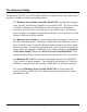
Table Of Contents
- Contents
- 1. Introduction
- The Harmony Family
- System Requirements
- The Product Package
- 2. Installation
- Installation Procedure
- Mounting Option
- LED Indicators
- Power Requirements
- 3. Wirefree Operation
- Harmony Architecture
- The IEEE 802.11b Specification
- Roaming Between Harmony 802.11b Access Points
- Roaming Guidelines
- 4. Configuration Parameters
- Basic Settings
- AP Name
- Physical Address
- Enable AP
- Partnered APC
- Channel
- Supported Clients
- SSID
- IP Addressing
- Security Settings
- WEP Encryption
- WEP Key Size
- WEP Keys
- Advanced Settings
- Supported Rates
- RTS/CTS
- 5. Performance Hints
- Microwave Ovens
- Range
- 6. Troubleshooting
- How to Obtain Help with Your LAN Installation
- LED Error Codes
- Common Problems and Solutions
- A. Parameters
- B. IEEE 802.11b Direct Sequence Channels
- C. Harmony 802.11b Access Point Specifications
- D. How to Reach Technical Support
- Index

10
Mounting Option
The Harmony 802.11b Access Point is designed to sit on a desktop. In addition, an
optional mounting bracket is available for purchase so that the unit may be mounted to
a wall or ceiling.
Follow these steps to attach the mounting bracket to the Access Point:
1. Remove the two rubber feet on the bottom of the Access Point. Note that the
rubber feet are attached to the unit with an adhesive.
2. Underneath the rubber feet there are three unthreaded mounting holes that accept
M5 thread forming screws. Align the holes of the mounting bracket with these
holes.
3. Locate the screws provided with the mounting bracket.
4. Insert the screws into the three holes of the mounting bracket and Access Point
(that is, the holes aligned in Step #2 above).
5. Tighten the screws with a screwdriver to attach the mounting bracket to the
Access Point.
LED Indicators
There are three LEDs on the top panel of the Harmony 802.11b Access Point, as shown
in Figure 1.
❑ Status LED: This LED, located on the left side (with the unit orientated so
that you can read the Proxim logo), is green when the unit is powered up and
operational. The LED is amber during initialization and when the Access
Point is not partnered with a Harmony AP Controller. This LED will blink red
in a repeating pattern if a problem occurs with the unit during operation. See
Chapter 6 for a discussion of these patterns.
❑ Radio LED: This LED, located in the center of the three LEDs, blinks green
when the Access Point receives data packets over its radio.