ORiNOCO® 802.
Copyright © 2012 Proxim Wireless Corporation, Milpitas, CA. All rights reserved. Covered by one or more of the following U.S. patents: 5,231,634; 5,875,179; 6,006,090; 5,809,060; 6,075,812; 5,077,753. This guide and the software described herein are copyrighted with all rights reserved. No part of this publication may be reproduced, transmitted, transcribed, stored in a retrieval system, or translated into any language in any form by any means without the written permission of Proxim Wireless Corporation.
Contents Preface . . . . . . . . . . . . . . . . . . . . . . . . . . . . . . . . . . . . . . . . . . . . . . . . . . . . . . . . . . . . . . . . . . . . . . . . . . . 1 4 Introduction . . . . . . . . . . . . . . . . . . . . . . . . . . . . . . . . . . . . . . . . . . . . . . . . . . . . . . . . . . . . . . . . . . . . . . . . . 6 About ORiNOCO® 802.11n Access Points . . . . . . . . . . . . . . . . . . . . . . . . . . . . . . . . . . . . . . . . . . . . . . . . . . . . . . . . . . . 6 Salient Features . .
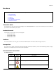
Preface Preface This chapter contains information on the following: • About this Guide • Products Covered • Audience • Prerequisites • Documentation Conventions • Related Documents About this Guide This guide gives a jump-start working knowledge on the ORiNOCO® 802.11n Access Points and details on their hardware specifications and installation procedures. Products Covered Listed below are the products covered in this guide.
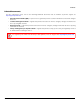
Preface Related Documents For more information, please refer to the following additional documents that are available at proxim’s support site http://support.proxim.com. • Quick Installation Guide (QIG) - A quick reference guide that provides essential information to install and configure the device. • Software Management Guide - A guide that provides instructions on how to configure, manage and monitor the device by using Web Interface.
1 Introduction This chapter contains information on the following: • About ORiNOCO® 802.11n Access Points • Salient Features • Multiple-Input-Multiple-Output 1.1 About ORiNOCO® 802.11n Access Points Proxim’s ORiNOCO® 802.11n Access Point family comprises the following products, that are designed to deliver flexible, scalable and reliable Data, Voice, and Video for small and medium Enterprise WLAN deployments. Product(s) Description ORiNOCO® AP-800 An indoor 802.
Introduction 1.3 Multiple-Input-Multiple-Output ORiNOCO® Access Point devices support Multiple-Input-Multiple-Output (MIMO) antenna technology that uses multiple antennas at both the transmitting end and receiving end to improve communication performance. The underlying technology of these access point radio(s) are based on a combination of MIMO and OFDM (Orthogonal Frequency Division Multiplexing). MIMO-OFDM combination radios solve interference, fading and multipath problems.
Hardware Overview and Installation 2 This chapter covers the hardware overview and installation procedures of the following products: • ORiNOCO® AP-800 and AP-8000 — Hardware Overview — System Requirements — Product Package — Installation Procedure • ORiNOCO® AP-8100 — Front View of the Device — Rear View of the Device — System Requirements — Product Package — Installation Procedure : • All the interface (radio) 2 parameters discussed in this chapter are applicable only to a dual-radio device.
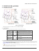
Hardware Overview and Installation 2.1 ORiNOCO® AP-800 and AP-8000 2.1.1 Hardware Overview ORiNOCO® AP-800 ORiNOCO® AP-8000 Figure 2-1 Device Overview Following sections give you a hardware overview of AP-800 and AP-8000. 2.1.1.1 LED Indicators Tabulated below are the four LEDs, that are available on the top panel of the device: LED Symbol Description Power LED This LED indicates whether the device is switched on/off. Ethernet LED This LED signals the traffic on the wired ethernet LAN.
Hardware Overview and Installation 2.1.1.3 Power Socket This socket connects to the 5 VDC power adapter. 2.1.1.4 Reset Reset button enables a user to powercycle the device. 2.1.1.5 Reload Reload feature helps to restore the device to factory default configuration, when: – The device cannot be accessed through web interface or command line interface. – The device does not initialize. – The password is lost.
Hardware Overview and Installation 2.1.3 Product Package Each shipment includes the items listed in the following table. Please verify that you have received all the parts in the shipment, prior to the installation. What’s in the Kit Image ORiNOCO® AP-800 or AP-8000 OR Omni-directional Antennas with reverse SMA connectors. • AP-800 : Quantity - 3 • AP-8000: Quantity - 6 Cable Security Cover Mounting Kit Quick Installation Guide (QIG) 2.1.3.
Hardware Overview and Installation 2.1.4 Installation Procedure Perform the following steps to install and mount the device. 2.1.4.1 Step 1: Install the Antennas The omni-directional antennas supplied with the product do not require any professional installation. Only, the regular outdoor antennas connected via a pigtail conversion cable, offering a standard connector type for antenna connection, require a professional installation.
Hardware Overview and Installation 3. Fasten the mounting plate by using a pair of plastic anchors and screws provided with the product package. 4. Hold the device with its rear panel facing up. Next, align two keyholes on the device with the two holders on the mounting plate. 5. Carefully slide the device down until the holders on the mounting plate fasten securely onto the keyholes of the device. Figure 2-4 Mount the Device Ceiling Mounting: To mount the device to ceiling, follow the following steps: 1.
Hardware Overview and Installation Serial Connection Optionally, you can connect a nine-pin, male-to-female serial cable to the console port/DB9 connector of the device for debugging and management. : • Use a straight-through ethernet cable, if you intend to connect the device to a switch, hub, or patch panel. • Use a cross-over ethernet cable or adapter if you intend to connect the device to a single computer. • The pin6 on RJ11 connector is used for power consumption and debugging.
Hardware Overview and Installation 2.2 ORiNOCO® AP-8100 2.2.1 Front View of the Device Figure 2-5 Front View of the Device The front panel of the device contains the following components: 2.2.1.1 LED Indicators Tabulated below are the four LEDs, that are available on the front panel of the device: LED Symbol Description Power LED This LED indicates whether the device is switched ON/OFF. Ethernet LED This LED indicates the status of the traffic over the wired ethernet LAN. 2.
Hardware Overview and Installation 2.2.2 Rear View of the Device Figure 2-6 Rear View of the Device The rear panel of the device contains the following components: 2.2.2.1 Ethernet Port The Ethernet port of the device allows the user to connect to the LAN by using CAT5e / CAT6 ethernet cable. 2.2.2.2 Power Socket This socket connects to the 12 VDC power adapter. 2.2.2.3 Keyhole A provision to fix the device onto the mounting plate. 2.2.2.4 Kensington Lock A security slot to lock the device. 2.2.2.
Hardware Overview and Installation 4. A 12V DC Power Adapter or a Power over Ethernet (PoE) Adapter. 2.2.4 Product Package Each shipment includes the items listed in the following table. Please verify that you have received all the parts in the shipment, prior to the installation. What’s in the Kit Image ORiNOCO® AP-8100 Mounting Kit Power Adapter (Supplied with country specific plug) * Supplied only with the WD SKU. Quick Installation Guide (QIG) 2.2.4.
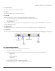
Hardware Overview and Installation 2.2.5 Installation Procedure Perform the following steps to mount and install the device. 2.2.5.1 Step 1: Plugging in the Cables Cabling with Power Adapter (Supplied with the product package) To plug in the cables by using a 12V DC power adapter: • Connect one end of the CAT5E/CAT6 Ethernet cable to the device’s ethernet port and the other end to a PC. • Plug the barrel of the power cable into the device’s power socket, only after the device installation is complete.
Hardware Overview and Installation Figure 2-7 Mounting Plate 2. Fasten the mounting plate by using a pair of plastic anchors and screws provided with the product package. 3. Hold the device in the upright position (with ‘Reload’ on top and the ‘LEDs’ at the bottom), such that the vent-holes on the device and the vent-holes on the mounting plate rest on each other. 4. Align the two keyholes on the device with the two holders on the mounting plate. 5.
Hardware Overview and Installation Figure 2-9 Ceiling Mounting Mounting AP-8100 to AP-800/8000 mounting plate (Optional) In case, you are mounting AP-8100 to an already installed AP-800/8000 Mounting Plate (P/N 67439), then follow the following steps. Wall Mounting: 1. Hold the device such that the ‘Reload’ is towards your right hand side and the ‘LEDs’ towards left hand side. 2. Align the two keyholes on the device with the two holders on the mounting plate. 3.
Hardware Overview and Installation 2.2.5.4 Step 4: View LEDs When the device is powered on, it performs startup diagnostics. When startup is complete, the LEDs show the operational state of the device. Tabulated below is the behavior of the four LEDs on the device. LED Power LED Symbol Behavior Color Glows green when the device is switched ON. • Glows green when the device is connected to a 1 Gbps link. • Blinks green when the traffic is being transmitted or received on the 1 Gbps link.
3 Hardware Specifications This chapter covers the hardware specifications of the following products: • ORiNOCO® AP-800 and AP-8000 • ORiNOCO® AP-8100 3.1 ORiNOCO® AP-800 and AP-8000 Category Specification Radio Module Single Radio Access Point (AP-800) / Dual Radio Access Point (AP-8000) 3x3 MIMO per radio Wireless Protocol 802.11a/n 802.11a 802.11g/n 802.11g Frequency 5.150 - 5.850 GHz* 2.4 - 2.483 GHz* * Subject to Individual Country Regulations Channel bandwidth 20MHz and 40MHz for 802.
Hardware Specifications Receive Sensitivity 11b 11a/g 11n Data Rate (Mbps) Receive Sensitivity (2.4-5Ghz) Data Rate (Mbps) Receive Sensitivity (2.4-5Ghz) Data Rate (MCS*) Receive Sensitivity (2.4-5Ghz) 1 -94 6 -96 MCS 0 -90 11 -91 36 -87 MCS 8 -91 - - 48 -83 MCS 10 -83 - - 54 -82 MCS 15 -72 *MCS refers to Modulation Coding Scheme.
Hardware Specifications 3.2 ORiNOCO® AP-8100 Category Specification Power Requirements Power Adapter: 12V/1.25A Power over Ethernet (PoE) (optional): 48V / Any 803.3af compliant Gigabit PoE Radio Module Dual Radio Access Point, 2x2 MIMO per radio Radio1: IEEE 802.11a/n Radio2: IEEE 802.11b/g/n Wireless Protocol 802.11a/n 802.11a 802.11g/n 802.11g Frequency 5.150 - 5.850 GHz* 2.4 - 2.483 GHz * Subject to Individual Country Regulations Channel bandwidth 20MHz and 40MHz for 802.11n 20MHz for 802.
Hardware Specifications Receive Sensitivity 11b 11a/g 11n Data Rate (Mbps) Receive Sensitivity (2.4-5Ghz) Data Rate (Mbps) Receive Sensitivity (2.4-5Ghz) Data Rate (MCS*) 1 -93 6 -90 11 -90 54 -75 Receive Sensitivity (2.4/5Ghz) 20 MHz 40 MHz MCS 0 -87 -86 MCS 7 -70 -66 * MCS refers to Modulation Coding Scheme. Remote Configuration Support Telnet and SSH, Web GUI (http) and SSL (https), TFTP SNMP v1, v2c and v3 SNMP trap and Syslog Message Authentication 802.
A Glossary and Abbreviations Glossary A Access point A wireless network transceiver or “base station” hub, often used to connect a local area network to one or more wireless devices. An access point (also called AP) can provide a communication link to a wired local area network also. Advanced Encryption Standard (AES) It is a symmetric-key encryption standard, containing three block ciphers AES-128, AES-192, AES-256.
Glossary and Abbreviations S ScanTool Proxim’s ScanTool is a software utility that runs on Microsoft Windows machine.
Glossary and Abbreviations W WPA Wi-Fi Protected Access is a Wi-Fi security standard that provides a high level of wireless network security. It uses data encryption through the Temporal Key Integrity Protocol (TKIP). TKIP scrambles the keys and ensures that the keys are not tampered with. User authentication is performed through the Extensible Authentication Protocol (EAP), to ensure that only authorized network users can access the network.
Glossary and Abbreviations O OFDM Orthogonal Frequency Division Multiplexing P PoE Power Over Ethernet PIFA Planar Inverted ‘F’ Antenna S SKU Stock Keeping Unit SNMP Simple Network Management Protocol SNTP Simple Network Time Protocol T TCP Transmission Control Protocol TFTP Trivial File Transfer Protocol TKIP Temporal Key Integrity Protocol U USM User Security Model W WLAN Wireless Local Area Networks WPA Wi-Fi Protected Access ORiNOCO® 802.
Statement of Warranty B Warranty Coverage Proxim Wireless Corporation warrants that its products are manufactured solely from new parts, conform substantially to specifications, and will be free of defects in material and workmanship for a Warranty Period of 1 year from the date of purchase.
Statement of Warranty Calls to the Customer Service Center for reasons other than product failure will not be accepted unless Buyer has purchased a Proxim Wireless Service Contract or the call is made within the warranty period. After the warranty period, Technical Support is fee based (detailed in Technical Services and Support).
Technical Services and Support C Obtaining Technical Service and Support If you are having trouble using the Proxim product, please read this manual and the additional documentation provided with your product.
Technical Services and Support Telephone Support Contact technical support via telephone as follows: USA and Canada Customers Phone: +1-408-383-7700; +1-866-674-6626 Business Hours: 24x7 live response. Tier 3 support: 8 a.m. to 5 p.m. M-F PDT (UTC/GMT -7 hrs) International Customers Phone: +1-408-383-7700; 0800-916475 (France); 8-800-100-9485 (Russia) Business Hours: 24x7 live response. Tier 3 support: 8 a.m. to 5 p.m.
Technical Services and Support – Priority Queuing * if units are out of standard warranty • 8 x 5 Enhanced ServPak – 8 x 5 Technical Support – Software Maintenance – Advanced Hardware Replacement – Extends Warranty* – Knowledge Base Access – Priority Queuing * if units are out of standard warranty ServPak Standalone Services • Extended Warranty ServPak • Advance Hardware Replacement ServPak Proxim Warranty vs.
Technical Services and Support Technical Support for Current Products after Warranty Period After the warranty period, technical support on products then being sold by Proxim will be based upon one of the following three options Customers can choose: • Customers can choose to purchase one of Proxim’s ServPak extended warranty and enhanced support packages for the product • Customers can choose to purchase one-time per-incident technical support for the product for a fee • Customers can choose to call