
Instruction manual

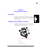
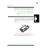
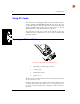
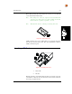

Table of Contents 2-iii
2325A137REFGD Revision B 2325 Reference Guide
Illustrations
Figure 2-1 Rotating the Laser Module ................................................................................. 2-1
Figure 2-2 Location of the Hardware Reset Mechanism..................................................... 2-5
Figure 2-3 Removing the PC Card Slot Cover.................................................................... 2-6
Figure 2-4 Typical PC Card................................................................................................ 2-7
Figure 2-5 Inserting a PC Card ........................................................................................... 2-7
Figure 2-6 Radio Card Antenna Connector......................................................................... 2-9
Figure 2-7 Radio Card Antenna Ports................................................................................. 2-9
Figure 2-8 Removing a PC Card....................................................................................... 2-10
Figure 2-9 The Serial Port................................................................................................. 2-11
Figure 2-10 Port for Tethered Scanner.............................................................................. 2-11
Figure 2-11 Antenna ......................................................................................................... 2-12
Figure 2-12 XFER Options (Xmodem Protocol) .............................................................. 2-16