Tsunami MP.
Tsunami MP.11a Antenna Installation Guide COPYRIGHT ©2003 Proxim Corporation, Sunnyvale, CA. All rights reserved. Covered by one or more of the following U.S. patents: 5,231,634; 5,875,179; 6,006,090; 5,809,060; 6,075,812; 5,077,753. This manual and the software described herein are copyrighted with all rights reserved.
Tsunami MP.11a Antenna Installation Guide Contents Copyright ...............................................................................................................................................................2 Trademarks............................................................................................................................................................2 Regulatory Information...................................................................................................
Tsunami MP.11a Antenna Installation Guide General Description ......................................................................................................................................44 Mounting Instructions....................................................................................................................................44 Specifications .............................................................................................................................................
Tsunami MP.11a Antenna Installation Guide About This Book This Tsunami MP.11a Antenna Installation Guide explains how to install and set up an outdoor antenna with the Tsunami MP.11a hardware. This guide does not explain how to erect antenna masts, nor how to install a safety grounding system. These prerequisites must be in place before installing the directional antenna. WHO SHOULD USE THIS GUIDE The installation of outdoor wireless links requires technical expertise.
Tsunami MP.11a Antenna Installation Guide Additional Files on Your Software CD-ROM All software CD-ROMs that come with your Tsunami products, include a readme.txt file. This file contains information about the software version and drivers. You are advised to print and read the readme.txt file prior to installing your Tsunami products, as it may contain additional information that was not available when this document was printed.
Tsunami MP.
Tsunami MP.11a Antenna Installation Guide Chapter 1.
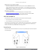
Tsunami MP.11a Antenna Installation Guide connect to N-type male connector pigtail extending from MP.11a unit Figure 3. Cable Setup for Indoor Installation On each end of the wireless link you will require the following items: ▪ A Tsunami MP.11a Base Station or Subscriber Unit ▪ A low-loss antenna cable to connect the indoor installation to the surge arrestor (optional) ▪ Female-female converter connector (optional) ▪ A surge arrestor to protect your sensitive Tsunami MP.
Tsunami MP.11a Antenna Installation Guide ▪ The location provides a connection to the network backbone (an Ethernet LAN cable that is connected to a hub, bridge, or directly into a patch panel) ▪ The location is as close as possible to the point where the antenna cable will enter the building (see “Placement of the Surge Arrestor” below). ▪ The ideal location has a temperature of 0-55 degrees Celsius and a maximum relative humidity (noncondensing) of 95%. CAUTION! The Tsunami MP.
Tsunami MP.11a Antenna Installation Guide ▪ The location allows for easy disconnection of the surge arrestor from the cable connected to the unit. ▪ The location provides a connection to the same grounding system as the Tsunami MP.11a hardware and the outdoor antenna mast (as described in “Grounding System” on page 16). Antenna Cable Route The antenna cable must be connected from the antenna through the surge arrestor to the pigtail connector of the MP.11a unit.
Tsunami MP.11a Antenna Installation Guide OVERVIEW OF THE OUTDOOR INSTALLATION The outdoor installation of the link (point-to-point or point-to-multipoint) requires the following: ▪ An antenna ▪ A low-loss antenna cable (available in three lengths) ▪ Antenna mast or wall bracket for the antenna ▪ An adequate grounding system that meets the requirements described in “Grounding System.
Tsunami MP.11a Antenna Installation Guide If any significant part of this zone is obstructed, a portion of the radio energy will be lost, resulting in reduced performance. Reduced performance can also occur when obstacles close to the antenna beam cause signal reflections or noise that interfere with the radio signal.
Tsunami MP.11a Antenna Installation Guide To minimize the influence of obstacles, signal interference, or reflections, note the following guidelines: ▪ Mount the antenna as high as possible above the “ground” to allow maximum clearance: º In open areas, “ground” is the actual surface of the earth. º In dense urban areas, “ground” is to be interpreted as the height of the highest obstacle in the signal path between the two antenna sites.
Tsunami MP.11a Antenna Installation Guide Antenna Mounting There are two ways to erect an antenna mast: Tripod Mount and Wall (Side) Mount. Tripod Mount The tripod mount is primarily used on peaked and flat roofs. The antenna mast must be secured to the roof using 3 or 4 guy wires equally spaced around the mast. When the height of the antenna mast is more than 3 meters (10 ft), you are advised to use at least three guy wires for each 3 meters (10 ft) section of the mast.
Tsunami MP.11a Antenna Installation Guide Chapter 2. Determining Range and Clearance When you read about wireless outdoor products, you often encounter the terms output power of the radio and gain of the antenna equipment as measures for the strength of the transmitted signal. ▪ Output power of radio equipment often depends on maximum limits as defined by local radio regulations; consequently, output power is, by definition, not the way to enhance wireless performance.
Tsunami MP.11a Antenna Installation Guide Maximum Range The maximum range of your Tsunami MP.11a system is based upon: ▪ ▪ ▪ The Type of Outdoor Antenna Equipment The Data Speed of the Wireless Link The clearance of the signal path (see “Clearance Factor” on page 18). The values in this section are based on calculations that assume optimal radio conditions. They do not represent a guarantee that the same maximum distance can be achieved at your location.
Tsunami MP.11a Antenna Installation Guide Note: The allowed antenna cables depend upon local radio regulations, the frequency, and the antenna gain used as listed in Table 5 on page 24 “Minimum Antenna Cable Loss in 5 GHz Bands.” Clearance Factor For optimal performance of your outdoor wireless link, the signal path between the Base Station Unit and Subscriber Unit must provide sufficient clearance.
Tsunami MP.11a Antenna Installation Guide In Figure 5, you see two variables that determine the shape of the antenna beam, also referred to as Fresnel Zone: ▪ The distance between the antennas (a) ▪ The clearance required for optimal performance (b), where clearance should be interpreted as: º Vertical clearance above the ground and the highest buildings or objects in the signal path º Horizontal clearance from neighboring buildings and objects in the signal path.
Tsunami MP.11a Antenna Installation Guide Figure 6. Clearance Factor Diagram CALCULATIONS Availability of the microwave path is a prediction of the percent of time that the link operates without producing an excessive bit error rate (BER) due to multipath fading.
Tsunami MP.
Tsunami MP.11a Antenna Installation Guide Procedure: 1. Start with the transmit power and the number of the channel to be used. From the output power tables (on page 23) find the dBm associated with this output power and channel. 2. Subtract the total loss of all transmission elements between the antenna and the radio on one side of the link (dB). (See “Minimum Antenna Cable Loss in 5 GHz Bands” on page 24.) 3. Add the dBi of the antenna you will be using.
Tsunami MP.11a Antenna Installation Guide An EIRP limit is the maximum RF energy that can be transmitted, as measured at the transmitting antenna, and is usually determined by government regulations. Table 2.
Tsunami MP.11a Antenna Installation Guide Table 4. Output Power Table for ETSI Frequency Band Channels 54 Mbps 48 Mbps 36 Mbps 6-24 Mbps 5.47 – 5.70 GHz 100, 104, 108, 112, 116, 120, 124, 128, 132, 136 14.5 15.5 17.5 18.5 Table 5. Examples of Antenna Cable Loss Required per Regulatory Domain and Antenna Type Frequency Band 5.25-5.35 GHz 5.25-5.35 GHz 5.25-5.35 GHz 5.25-5.35 GHz 5.725-5.85 GHz 5.725-5.85 GHz 5.725-5.85 GHz 5.725-5.85 GHz 5.725-5.85 GHz 5.725-5.85 GHz 5.725-5.85 GHz 5.725-5.
Tsunami MP.11a Antenna Installation Guide Table 6. Distance and Link Budget Reference Frequency: 5600 MHz Center Frequency for Europe Link Budget (dB) Distance (m) Fresnel Zone Link Budget (m) (dB) Distance (m) Fresnel Zone Link Budget (m) (dB) Distance (km) Fresnel Zone (m) 61 4.8 0.3 91 151 1.4 62 5.4 0.3 92 170 1.5 121 4.8 8.0 122 5.4 63 6.0 0.3 93 190 8.5 1.6 123 6.0 64 6.8 0.3 94 9.0 214 1.7 124 6.8 9.5 65 7.6 0.3 66 8.5 0.3 95 240 1.8 125 7.6 10.
Tsunami MP.11a Antenna Installation Guide Chapter 3. Installing the Antenna PLANNING ANTENNA INSTALLATION Plan the day for your outdoor antenna installation carefully. Do not install the antenna in wet or windy conditions, during a thunderstorm, or when the area in which the equipment is to be installed is covered with ice or snow. The grounding system for the antenna mast, Tsunami MP.11a hardware, and surge arrestor should be installed before the cable from the antenna is connected to the surge arrestor.
Tsunami MP.11a Antenna Installation Guide Antennas shall be mounted in such a manner to minimize the potential for human contact during normal operation. In order to avoid the possibility of exceeding the FCC radio frequency exposure limits, human proximity to the antenna shall not be less than 20 cm (8 inches) during normal operation. The low-loss antenna cable that will connect the antenna with the surge arrestor must be at least 1 m (3 ft) away from any high voltage or high current cable.
Tsunami MP.11a Antenna Installation Guide MOUNTING THE ANTENNA Proxim Corporation offers multiple antennas to set up a wireless link. As the mounting procedures for the various antennas differ from one another, consult the documentation you received from the antenna manufacturer for mounting procedures. When mounting multiple antennas on a single mast, use the following methods to minimize the influence of cross-talk interference between the antennas: ▪ ▪ Place your antennas as far apart as you can.
Tsunami MP.11a Antenna Installation Guide Sealing the Cable Connectors Most problems associated with wireless outdoor installations are related to degrading performance due to corrosion of the antenna cable and cable connectors. To avoid this type of problem, you must always seal the cable connectors that are located outdoors using the weatherproofing tape provided.
Tsunami MP.11a Antenna Installation Guide Antenna Alignment For optimal performance of your wireless link, make sure the antennas are properly aligned (facing one another “eye-to-eye”). To align the antennas: ▪ Use a pair of binoculars or a map of the area and a compass to point the antennas to one another. ▪ Use the Link Test option of the management tools that come with the Tsunami MP.11a to analyze the radio link quality.
Tsunami MP.11a Antenna Installation Guide Antenna Cable Routing The antenna cable must be routed and fixed in such a way that installation technicians have a clear passage area. All connectors that are located outdoors must have a weatherproof seal. You are advised to seal connectors only after you have completed the final radio tests. BEFORE CLIMBING THE ROOF... Before you start installing, check whether you have all the required components to set up an outdoor wireless link.
Tsunami MP.11a Antenna Installation Guide Appendix A. Outdoor Antenna Equipment As described previously, Proxim Corporation offers different types of outdoor antennas and cable lengths for your network design. The directional antennas provide maximum range, but due to their narrow beamwidth, these antennas require precise antenna alignment to achieve optimal performance. The higher the antenna gain, the more precise the alignment should be.
Tsunami MP.11a Antenna Installation Guide ANTENNA LIST Table 7. Antenna List Type Manufacturer Model Number Omni Stella Doradus Stella Doradus Stella Doradus Stella Doradus 52 52 58 58 Sector SmartAnt Mars R0320-057 MA-WC50-5X Panel SmartAnt SmartAnt SmartAnt SmartAnt R0320-056 R0320-091 R0209-116 R0209-149 1-Foot Flat Panel Gabriel Andrew Mars 2-Foot Flat Panel 2360 3360 2360 3360 Frequency Range Mid-Band Gain 5.200 – 5.300 MHz 5.200 – 5.300 MHz 5.700 – 5.900 MHz 5.700 – 5.
Tsunami MP.11a Antenna Installation Guide Appendix B. Antenna Cabling System OUTDOOR CABLING COMPONENTS To connect your Tsunami MP.11a hardware to an outdoor antenna installation, you will need the following cabling components: ▪ Surge arrestor ▪ Low-loss antenna cables ▪ One of the outdoor antennas described in Appendix C. When purchasing new Tsunami MP.11a products, each of these components will be equipped with standard N-type connectors.
Tsunami MP.11a Antenna Installation Guide Note: Previously marketed Tsunami outdoor antenna systems in FCC regulated countries (such as the USA and Canada) were shipped with a different cabling system, identified by reverse polarity-N connectors (depicted in the following table). Table 9. Reverse Polarity-N Cabling Diagram Cabling Component Reverse Polarity-N Cabling Systems a Pigtail attached to MP.
Tsunami MP.11a Antenna Installation Guide Check with a qualified electrician if you are in doubt whether the surge arrestor and cable connectors are properly grounded. Only after you have verified that each of the items is properly grounded, replace the surge arrestor and disconnect the cables from the grounding system in exactly the reverse order of the previous steps.
Tsunami MP.11a Antenna Installation Guide 6. Use the hex-nut (item f) to secure the surge arrestor in its position. Ensure that the surge arrestor is properly connected to the grounding system. CAUTION! To avoid damage to electronic equipment and your Tsunami MP.11a equipment always apply the surge arrestor between the outdoor antenna installation and the Tsunami MP.11a hardware or other computing device that is connected to the outdoor antennas. Table 10.
Tsunami MP.11a Antenna Installation Guide Table 11. Specifications 6 m (20 ft) Antenna Cable Mechanical Length 6 meter (20 ft) Connectors Standard-N (male on both ends) Operating Temperature -40°C (-40°F) to +85°C (+185° F) Diameter (1) 5 mm (0.2 in) 10 mm (0.4 in) Weight 32.75 g/m (0.022 lbs/ft) 101.2 g/m (0.068 lbs/ft) Bend Radius 50 mm (2 in) 100 mm (4 in) Insertion Loss at 5.8 GHz 0.80 dB/m (26.4 dB/100 ft) 0.33 dB/m (10.8 dB/100 ft) Total for this cable <6.0 dB Electrical < 3.
Tsunami MP.11a Antenna Installation Guide Table 13. Specifications 22 m (75 ft) Antenna Cable Mechanical Length 22 m (75 ft) Connectors (1) Standard-N (male on both ends) Operating Temperature -40°C (-40°F) to +85°C (+185° F) Diameter 10 mm (0.4 in) Weight 101.2 g/m (0.068 lbs/ft) Bend Radius 100 mm (4 in) Electrical Insertion Loss 0.33 dB/m (10.8 dB/100 ft) at 5.8 GHz Total for this cable < 8.7 dB Table 14.
Tsunami MP.11a Antenna Installation Guide Appendix C. Recommended Antennas 18 DBI HIGH GAIN DIRECTIONAL PANEL ANTENNA FOR 5.25 TO 5.875 GHZ Pictured: SmartAnt antenna Specifications Electrical Frequency Range 5.25-5825 MHz VSWR 1.
Tsunami MP.11a Antenna Installation Guide Dimensions Pattern Appendix C.
Tsunami MP.11a Antenna Installation Guide Appendix C.
Tsunami MP.11a Antenna Installation Guide Appendix C.
Tsunami MP.11a Antenna Installation Guide 15 DBI HIGH GAIN DIRECTIONAL PANEL ANTENNA FOR 5 GHZ Pictured: SmartAnt antenna General Description This window antenna is a high-gain antenna for the 5 GHz frequency band. This antenna is typically used in combination with a Subscriber Unit. The red heat-shrink tube at the antenna connector of this antenna matches the red heat-shrink tube at the MP.
Tsunami MP.11a Antenna Installation Guide Specifications Electrical Environmental and Mechanical Frequency range 5150 MHz – 5850 MHz Survival wind speed 180 km/hr Gain* 15 dBi Temperature -40º C to +80º C VSWR 2.0 : 1 Max. Humidity 95% @ 25º C Polarization Linear, vertical Lightning Protection DC ground HPBW / horizontal 45 degrees Radome color white HPBW / vertical 10 degrees Radome material ABS, UV resistant Front to back ratio 18 dB Weight 0.
Tsunami MP.11a Antenna Installation Guide 23 DBI HIGH GAIN DIRECTIONAL PANEL ANTENNA FOR 5.8 GHZ Pictured: SmartAnt antenna Package Contents ▪ ▪ ▪ ▪ ▪ ▪ Antenna Extension Cable (50cm) Mounting Kit Surge Protector Water-proof tape Quick Installation Guide Mounting Appendix C. Recommended Antennas CPN 65756B 1. 2. 3. 4. 5. 6. 7. 8. 9.
Tsunami MP.11a Antenna Installation Guide Specifications Electrical Frequency Range 5725 - 5875 MHz Nominal Impedance 50 ohms Gain 23 dBi Front-to-Back Ratio 40 dB HPBW/vertical 9 degrees HPBW/horizontal 9 degrees Cross Polarization 25 dB Power handling 20 W (cw) Connector Standard N female VSWR 1.
Tsunami MP.11a Antenna Installation Guide Pattern Appendix C.
Tsunami MP.11a Antenna Installation Guide Appendix C.
Tsunami MP.11a Antenna Installation Guide Appendix D. Certified Outdoor Solutions INTRODUCTION As radio regulations differ between the various countries world-wide, not all of the outdoor solutions described in this Tsunami Outdoor Antenna Installation Guide may be allowed in the country where you plan to install this equipment. Local radio regulations or legislation may impose restrictions on the use of specific combinations of: ▪ ▪ Low-loss antenna cables and outdoor antennas.
Tsunami MP.11a Antenna Installation Guide Appendix E. Channel Frequencies The following table shows MP.11 (802.11b) channel allocations that vary from country to country. Values listed in bold indicate default channels and frequencies. Channel ID FCC/World (GHz) ETSI (GHz) France (GHz) Japan (GHz) 1 2.412 2.412 -- 2.412 2 2.417 2.417 -- 2.417 3 (default in most countries) 2.422 2.422 -- 2.422 4 2.427 2.427 -- 2.427 5 2.432 2.432 -- 2.432 6 2.437 2.437 -- 2.437 7 2.
Tsunami MP.
Tsunami MP.11a Antenna Installation Guide WARRANTY AND REPAIR If it appears that your unit needs a repair or replacement, return the unit to your Dealer or Distributor in its original packaging.
Tsunami MP.