2 RangeLAN2 Serial Adapter Models 7910 and 7911 User’s Guide
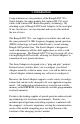
Copyright © 1999 Proxim, Inc., Sunnyvale, CA. All rights reserved. This manual and the software described in it are copyrighted with all rights reserved. No part of this publication may be reproduced, transmitted, transcribed, stored in a retrieval system or translated into any language in any form by any means without the written permission of Proxim, Incorporated. Trademarks RangeLAN, the RangeLAN logo, RangeLAN2, and Proxim are trademarks of Proxim, Inc.
Warranty Return Policy If you have a problem with your RangeLAN2 product, please call Proxim Technical Support at (408) 731-2640. Proxim Technical Support will assist with resolving any technical difficulties you may have with your Proxim product. If your product is found to be defective, you may return the product to Proxim after obtaining an RMA (Return Materials Authorization) number from Proxim Technical Support. The product must be returned in its original packaging.
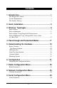
Contents 1. Introduction ................................................................. 1 The RangeLAN2 Family ......................................................................... 2 System Requirements .............................................................................. 3 The Product Package ............................................................................... 3 2. Quick Installation ........................................................ 5 3. Wireless Topologies ..............
10. Advanced Configuration Menu .............................. 55 Advanced Parameters ............................................................................ 56 11. Display Parameter Values ...................................... 61 12. View Statistics ......................................................... 63 Serial Errors Statistics ........................................................................... 64 Packetized Mode Statistics ..............................................................
D. Parameters .............................................................. 107 Radio Parameters ................................................................................. Network Parameters ............................................................................. Serial Parameters ................................................................................. Advanced Configuration Parameters ................................................... 107 108 109 110 E.
1. Introduction Congratulations on your purchase of the RangeLAN2 791x Serial Adapter, the radio module that replaces RS-232 serial cables with wireless RF (Radio Frequency) technology. By attaching a pair of RangeLAN2 Serial Adapters to the serial port of any two devices, you can transmit and receive data without the use of wires. The RangeLAN2 791x can support several data rates and uses the same patented 2.
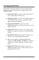
The RangeLAN2 Family RangeLAN2 791x Serial Adapter is part of a family of highperformance products that provides a complete wireless networking solution. ❑ RangeLAN2 7100 is a wireless LAN adapter that fits into a standard PC/AT ISA bus slot. ❑ RangeLAN2 7400 is a wireless LAN adapter which fits into a PCMCIA Type II slot on a portable notebook, laptop, or pen-based computer. ❑ RangeLAN2 7510/752x Access Points allow RangeLAN2 products to seamlessly connect to a wired Ethernet network.
System Requirements To begin using your RangeLAN2 791x Serial Adapter, you need the following minimum system requirements: ❑ At least one (1) device with a free RS-232 (serial) port (terminal, PC, etc.). ❑ At least one (1) other RangeLAN2 product. If the Serial Adapters are acting as a replacement for a serial cable, this additional RangeLAN2 product must be a second 791x Serial Adapter which will attach to a free RS-232 port on another device.
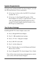
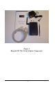
Figure 1 RangeLAN2 791x Serial Adapter Components 4
2. Quick Installation You may follow the quick installation and configuration steps if all of the following conditions are true: ❑ You will use all of the software default values. ❑ You are using two (2) RangeLAN2 Serial Adapters as a replacement for an RS-232 cable. ❑ You are using no more than nine (9) pairs of Serial Adapters in one location. Follow the steps below to install two RangeLAN2 791x Serial Adapters: 1. Firmly screw the antenna onto its connector in a clockwise rotation.
Figure 2 Attachment of the RangeLAN2 Serial Adapter Antenna 2. Attach one end of an RS-232 cable to the RangeLAN2 Serial Adapter and the other end to a free serial port of a communication device, such as a terminal or a computer. Perform this step with both Serial Adapters. 3. Each RangeLAN2 791x Serial Adapter is preconfigured to operate as a Station. Therefore, before two Serial Adapters will communicate, one must be set as a Master.
4. Each RangeLAN2 791x Serial Adapter is preconfigured to use Domain 0. If you have multiple pairs of Serial Adapters and each pair consists of one Master and one Station, set each pair to a unique Domain number. Using the Domain rotary switch on the underside of the RangeLAN2 Serial Adapter, set each pair to a unique Domain number from 0-8 to ensure minimal interference.
8
3. Wireless Topologies The RangeLAN2 Serial Adapter supports numerous wireless topologies. The following sections describe four (4) basic wireless configurations supported by the RangeLAN2 Serial Adapter: Point-to-Point, Point-to-Multipoint, Point-to-Point using RangeLAN2 Infrastructure, and Point-to-Multipoint using a RangeLAN2 Access Point as a Base Unit. Point-to-Point In this topology, a pair of RangeLAN2 Serial Adapters are configured to exclusively communicate with each other.
In Figure 3 above, Serial Adapters 1 and 2 can communicate with each other, as can Serial Adapters 3 and 4. Even though all four units may be in range of one another and may “hear” the others’ messages, each unit will filter out messages not intended for it. Since this topology establishes a one-to-one, MasterStation relationship between two Serial Adapters, it acts as a wireless substitute for an RS-232 cable in a wide variety of applications.
Point-to-Multipoint The RangeLAN2 Serial Adapter may also operate in a Point-toMultipoint topology. This configuration provides added flexibility, allowing one centralized unit, operating in Packetized mode, to communicate with multiple units placed in remote locations. When operating in Packetized mode, a central Serial Adapter may be programmed to send either directed messages or broadcasts to other Serial Adapters, by specifying the appropriate IP address and send mode.
Figure 4 Point-to-Multipoint 12
Point-to-Point Using RangeLAN2 Infrastructure You may also use your existing RangeLAN2 infrastructure and network to increase the range and flexibility of communications between Serial Adapters. A Serial Adapter configured as a Station may synchronize to a RangeLAN2 Access Point which has the same Domain and Security ID. Two Serial Adapters which are positioned out of range of one another, can be set as Stations so that each will synchronize to a RangeLAN2 Access Point.
Figure 5 Point-to-Point Using RangeLAN2 Infrastructure 14
Point-to-Multipoint Using a RangeLAN2 Access Point as a Base Unit A Serial Adapter may communicate directly with a workstation that has either a RangeLAN2 ISA card, a RangeLAN2 PC card, or is on the same Ethernet segment as a RangeLAN2 Access Point. One configuration that utilizes this feature is Point-toMultipoint using a RangeLAN2 Access Point to connect a wired desktop computer to a number of remote Serial Adapters.
Figure 6 above shows a simple configuration of this topology. Desktop 1 is on the same network as a RangeLAN2 Access Point. Serial Adapters 1 and 2 are configured as Stations and are synchronized to the Access Point, which is configured as a Master. Desktop 1 is running a custom-made application written in a programming interface, such as Windows Sockets, which uses TCP/IP to communicate with either or both Serial Adapters.
4. Pass-through and Packetized Modes The Serial Adapter’s serial interface can be set for two kinds of operating modes: Pass-through mode and Packetized mode. The format of the information presented to the unit’s serial port is dramatically different depending on which of these modes is selected. You should use the Pass-through mode for applications where a pair of RangeLAN2 Serial Adapters replace an RS-232 cable without changing the existing serial application.
18
5. Understanding the Hardware Rotary Switches The RangeLAN2 Serial Adapter is designed for easy configuration by setting two rotary switches located on the bottom of the unit. The rotary switches are shown in Figure 7 below. Use the switch setting tool, enclosed in the product package, to change the position of the rotary switches. ❑ The Station/Master Switch allows the user to externally set the unit as either a Master or a Station within a wireless network.
Domain Switch Station/Master Switch Figure 7 Rotary Switches The Pairing Domain There is an additional feature associated with Domain 8 on the Domain Switch called the Pairing Domain. When the Pairing Domain is not used, two Serial Adapters will each send out a series of handshaking messages and exchange IP addresses to enable communication during boot-up.
when the unit is reset. This allows the user to permanently configure a pair of Serial Adapters to communicate exclusively with one another. Follow these steps to permanently bind a pair of Serial Adapters: 1. Ensure that both units are turned off. 2. Using the switch setting tool, turn the Domain Switch to 8 on both units.
To reset the unit back to the default setting, manually set the Destination Address to 0.0.0.0 or reset the unit to factory defaults from within the software configuration menu. When using this feature, have only two Serial Adapters configured to Domain 8 on the rotary switch at any point in time. If only one unit is configured for Domain 8, the Pairing Domain will not change the unit’s configuration.
❑ The Serial LED on the left side blinks green when the Serial Adapter is transmitting data over the serial connection.
There are also four LEDs on the back panel of the RangeLAN2 791x Serial Adapter: ❑ The green Master LED, located between the DC power jack and the serial interface, is on steady when the unit is set as a Master. ❑ The yellow Sync LED, located between the DC power jack and the serial interface, is on steady when the unit is set as a Station and is synchronized to a Master.
Override LED Sync LED Figure 9 Back Panel LEDs 25 Master LED
Serial Port Specification Figure 10 and the table below provide the specification of the 9pin serial port located on the RangeLAN2 Serial Adapter. The Serial Adapter is wired as a DCE (Data Communication Equipment), like a modem. The unit is designed to connect directly to a DTE (Data Terminal Equipment), such as a computer or dumb terminal, using a straight-through RS-232 cable.
Figure 10 Serial Port Specification 27
Antenna Options The Serial Adapter is shipped with a standard directly-connected antenna. To install the antenna, screw it clockwise onto the antenna connector. Proxim sells several antenna alternatives, including higher gain omnidirectional and directional antennas. Each of these antennas ship with installation and mounting instructions. For information on additional antenna options, please contact your Proxim Sales Representative. Mounting Options The Serial Adapter was designed to sit on a flat surface.
2.75” 2.
30
6. Configuration You need to configure the RangeLAN2 Serial Adapter using the software menus if any of the following conditions apply: ❑ You plan to operate a Serial Adapter in broadcast mode. ❑ You want to set Security IDs on your Serial Adapters. ❑ You want to operate in Packetized mode. ❑ You need to change the software default values, including IP addresses.
3. Apply power to the Serial Adapter. When the unit is ready for operation, the letter “U” will be displayed on the terminal screen. Let the unit sit idle for one second and type “$$$”.
Type the number of the menu option and to view the sub-menus. Hit at any time to back up one menu. To simplify the menu options, all of the configuration menus will appear in a tree diagram format within this manual.
34
7. Radio Configuration Menu This section discusses the Radio Configuration values that can be manually configured by the user.
Radio Parameters The table below shows the range and default values for each of the Radio parameters: Parame te r Name Rang e De fault Do main 0-15, and "U" fo r Use Switch Use Switch Channe l * 1-15, and 0 fo r auto matic se le ctio n 0 Sub channe l * 1-15 1 Statio n Typ e Maste r, Statio n, and "U" fo r Use Switch Use Switch Maste r Name * 11 characte rs MASTER Se curity ID 20 characte rs b lank Enab le Re p e ating * Y/ N N MAC Op timize * No rmal, Lig ht, Ve ry Lig ht, and Auto
Note that changes to these parameters will not take effect until either the radio or the Serial Adapter is reset. A RangeLAN2 Serial Adapter may be set as either a Master or a Station using the Station Type parameter within the configuration menu. You may also choose “U” for Use Switch to use the value specified by the Station/Master Switch. The rotary switch is set to Station by default. Proxim’s RangeLAN2 products are frequency hopping spread spectrum radios which communicate in the 2.
In order to establish communications, all Stations and the Master must be configured with the same Domain number. Radios on different Domains cannot communicate with each other. The Domain is a software filter which does not affect the actual radio frequency or the frequency hopping sequence. You typically want to set each Serial Adapter in a given network to the same Domain.
Each Master can select one of 15 Channels to establish communication with its Stations. Each Channel number sets a unique frequency hopping sequence allowing for multiple subnetworks with higher data rate transmission capability in the same air space. You may think of the Channel as a pipe. In order to communicate, radios must be on the same Channel and there must be one (and only one) Master that provides the timing for that Channel.
For example, you can use Channel 1, Subchannel 1 for Adapter Pair A and Channel 1, Subchannel 2 for Adapter Pair B. The two pairs will not communicate with one another. However, they are still sharing the 1.6 Mbps pipe since they are both using Channel 1. The Subchannels are designated 1 through 15, and 1 is the default setting. This parameter is visible only when the Serial Adapter is set as a Master.
The Repeating Enabled parameter gives the ability to enable or disable the RangeLAN2 repeating feature. When enabled, a Serial Adapter, acting as a Master, may repeat signals coming from one Station and destined for another Station. These two Stations must be out of range of one another, but both in range of the Master Serial Adapter for repeating to occur. However, be aware that by enabling the repeating feature, the network throughput will drop by as much as one-half when repeating occurs.
There is no inactivity timeout set by default, but you may change this to any interval of 10 seconds. This parameter is visible only when the Serial Adapter is set as a Station. A Master unit does not have a sleep mode. Note: Configuring a Serial Adapter with an Inactivity Timeout may cause data loss if any of your units are operating in UDP or UDP Broadcast mode.
You may choose to disable a Serial Adapter’s ability to roam with the Roaming Enabled parameter. This feature is enabled by default; however, if you want a RangeLAN2 Serial Adapter to communicate with one and only one other RangeLAN2 product, you may disable this feature. This parameter is visible only when the Serial Adapter is set as a Station.
44
8. Network Configuration Menu This section describes the network configuration parameters for the RangeLAN2 Serial Adapter.
Network Parameters Parame te r Name Rang e De fault Se nd Mo d e TCP (Po int to Po int), UDP (Po int to Po int), and Bro ad cast TCP(Po int to Po int) De stinatio n Ad d re ss - - IP Ad d re ss - De fault ad d re ss Sub ne t Mask - 255.0.0.0 Lo cal Po rt Numb e r - 5000 Re mo te Po rt Numb e r - 5000 De fault Gate way Ad d re ss - 0.0.0.0 Send Mode indicates the method which a RangeLAN2 Serial Adapter will use to communicate with other RangeLAN2 units.
broadcast message. Broadcast mode uses the UDP transport layer protocol to send data. As stated above, UDP is faster than TCP but does not ensure reliable message delivery. However, if your application ensures the reliability of data transmission, there should be no negative side effects to using the UDP protocol in either Point-to-Point or Broadcast mode. See Chapter 3 for a detailed discussion of the suggested Wireless Topologies.
cate with the wired infrastructure, it will be necessary to change the default address to one which is on the same subnet as the wired stations so that IP packets are routed correctly. You can override the default address using the IP Address option in the configuration menu. This parameter will not change unit the Serial Adapter is reset. Subnet Mask indicates the mask that will be used to determine on which network the RangeLAN2 Serial Adapter is located.
9. Serial Configuration Menu This section describes the serial configuration parameters for the RangeLAN2 Serial Adapter.
Serial Parameters Parame te r Name Rang e De fault Baud Rate (b p s) 300,1200, 2400, 4800, 9600, 19200, 38400, 57600, and 115200 9600 Parity Eve n, Od d , Mark, Sp ace , and No ne No ne Numb e r o f Sto p Bits 1-2 1 Numb e r o f Data Bits 7-8 8 Echo Mo d e No ne , Simp le , and Te rminal No ne Flo w Co ntro l Ge ne rate o r Re co g nize XON/XOFF, Ge ne rate CTS, Ge ne rate DSR, Re co g nize DTR, and Re co g nize RTS Ge ne rate CTS and Ge ne rate DSR Max Line Le ng th 1-1456 1456 Inp
You may also change the default settings for Parity, Number of Stop Bits, and Number of Data Bits to match the settings of your RS-232 application. The Serial Adapter will support any combination of 7 or 8 data bits, 1 or 2 stop bits, and one of the following parity settings: even, odd, mark, space, and none. The Serial Adapter supports three Echo Modes: None, Simple, and Terminal. When no Echo is selected, the unit will not Echo the characters typed to the terminal screen.
CTS pin, notifying the remote RS-232 host that data may be sent over the connection. This function regulates the data exchange between two RS-232 hosts. In addition to this basic function, the Serial Adapter’s flow control options regulate the data exchange between the Serial Adapter and its attached RS-232 host.
The Maximum Line Length refers to the maximum number of characters the Serial Adapter must receive before transmitting the message. The maximum value for this parameter is 1456, which corresponds to the maximum size of an Ethernet packet minus the space required for the transport layer and other headers. Setting this parameter to 1 will cause the unit to transmit each character as a separate packet as soon as the unit receives it.
54
10.
Advanced Parameters Parame te r Name Rang e De fault IP Ad d re ss Filte r - - Acce p t Bro ad cast Packe ts Ye s/No Ye s Acce p t Po int-to -Po int Packe ts Ye s/No Ye s Escap e -to -Me nu Characte r - $ Escap e -to -Me nu De lay Incre me nts o f 0.
The IP Address Filter parameter allows you filter out packets received by the Serial Adapter from any IP Address other than one specified IP Address. You may specify only one IP Address from which to accept messages. The default for this parameter is to receive packets from any IP Address. The configuration menu allows you to apply Packet Type Filters to limit the type of messages the unit receives. You may chose to filter either Point-to-Point or Broadcast messages.
and loses communication with its destination unit. You may set the unit to either reestablish the connection and continue transmissions or to halt communications to provide an alert that the connection has been lost. If the Serial Adapter loses communication while set to Continue, the unit will try to reestablish communication. If the unit loses communication when set to Halt, the Status LED on the top of the unit will blink once in a repeating pattern until the unit is reset.
If you have written, or plan to write, a custom application to allow communication between the RangeLAN2 Serial Adapter and an Ethernet device, set the TCP Close Connection Signal parameter to “Yes.” When this parameter is enabled, the Serial Adapter will close an existing TCP connection upon receipt of the “$QUIT” command from a remote workstation.
60
11. Display Parameter Values The Serial Adapter displays all of the relevant parameters in one centralized location. By choosing “Display Parameter Values,” you can view the current and configured values for the Radio, Network, Serial, and Advanced parameters. Current values are already in use by the Serial Adapter. If the configured value is different from the current value, the Serial Adapter must be reset before the configured value takes effect.
Serial Adapter Main Menu Display P arameter V alues R adio Parameters N etw ork P arameters S erial P arameters Baud R ate (current) Baud R ate (configured) P arity (current) P arity (configured) # S top Bits (current) # S top Bits (configured) # Data Bits (current) # Data Bits (configured) E cho Mode Max.
12. View Statistics You can view statistics about the RangeLAN2 Serial Adapter from the View Statistics menu.
Serial Errors Statistics This category displays the number of errors occurring in the serial interface of the Serial Adapter during operation. The Serial Adapter will record the number of framing errors that occur when a character is received over the serial line without a valid stop bit. A parity error occurs when the parity check (i.e., even, odd, mark, or space) failed for a received character.
13. Performance Hints This section provides the user with ideas for how to increase performance with Proxim wireless products. Microwave Ovens Microwave ovens operate in the same frequency band as RangeLAN2 products. Therefore, if you use a microwave within range of RangeLAN2 equipment, you may notice network performance degradation. However, both your microwave and your RangeLAN2 network will continue to function. Range Every environment is unique with different obstacles, barriers, materials, etc.
Proper antenna placement can help improve range. Here are some guidelines: ❑ The antenna should be placed in a vertical position. ❑ Do not place a sheet of metal (like a filing cabinet) between two antennas. ❑ Two antennas that are communicating should be in the same plane. For example, do not lie one antenna on its side and have its partner standing upright.
14. Troubleshooting The RangeLAN2 791x Serial Adapter is designed to be very easy to install and operate. If you do experience difficulties, however, use the information in this chapter to help diagnose and solve the problem. If you cannot resolve the problem, contact Proxim, as described in Appendix G, “How to Reach Technical Support.” How to Obtain Help with Your Installation If you require assistance to install your Serial Adapter, Proxim can put you in touch with a RangeLAN2 Reseller in your area.
3 blinks: Software error 4 blinks: Failed to initialize the radio 5 blinks: Memory full 6 blinks: Miscellaneous error 7 blinks: Failed to initialize the TCP/IP stack Commonly Asked Technical Support Questions Pro b le m/Symp to m Que stio n Po ssib le So lutio n/Answe r Chap te r in Use r' s Guid e The Se rial Ad ap te rs are no t co mmunicating . 1. Che ck to e nsure that the Do main Switch is no t se t to 9 o n e ithe r unit. 2. Ve rify that ne ithe r unit is se t in the co nfig uratio n me nu. 3.
Pro b le m/Symp to m Que stio n Po ssib le So lutio n/Answe r Chap te r in Use r' s Guid e I can' t b ring up the Co nfig uratio n Me nu. 1. Ve rify that yo ur te rminal se tting s match tho se se t o n the Se rial Ad ap te r. 2. Ensure that yo u are using a RS232 cab le to co nne ct the Se rial Ad ap te r that co nfo rms to the Se rial Ad ap te r Pin Sp e cificatio n as sho wn in Chap te r 5. 3. Be sure to o nly typ e o nly thre e "$" symb o ls in rap id succe ssio n.
A. Packetized Mode Specification Overview The purpose of the Serial Adapter is to accept information from a serial line and transmit it reliably via radio to another RangeLAN2 station, or to a wired station through a RangeLAN2 Access Point. Serial Adapters receiving information transfer it to an external computer (“External Computer”) via their own serial lines.
tions where developing special software to interact with the Serial Adapter is undesirable. For some applications, the Pass-through mode of operation is not ideal. For example, because the Pass-through Serial Adapter takes all information arriving at its serial line as data to be sent out over the radio network, it is not possible to change the Serial Adapter’s configuration on the fly by sending it commands over the serial line.
The Modem Command Protocol (MCP) is an application layer protocol by which an External computer may exchange commands, status information, and data with the Serial Adapter over the Serial Adapter’s RS-232 serial line. Since the protocol is an application layer protocol, it contains no provision for error recovery over the serial line. This problem of error recovery is a layer 2 problem and is handled by the Proxim layer 2 serial protocol, the PPX-1.
PPX-1 Protocol The following is the format of the PPX-1 packet: BYTE SOH BYTE BYTE BYTE LEN H LEN L HEADER CHECK BYTES DATA BYTE CHECKSUM H CHECKSUM L BYTE ;Start of header for synchronization (ASCII 01H) ;High byte of length ;Low byte of length ;= NOT(LEN L) + ;NOT(LEN H), this is an ; arithmetic sum ;This is where the MCP COMM;AND is contained (see section 3) ;16 bit check sum of data Note that the LEN field is the length of the DATA section, not including the CHECKSUM field.
Modem Command Protocol (MCP) This section describes the Modem Command Protocol. All of the commands which the Serial Adapter will accept are listed below. Each command begins with a command byte which tells the Serial Adapter which command the message contains. Some commands cause the Serial Adapter to produce a response packet at a later time. The format of all possible Serial Adapter responses is listed in the section entitled “MCP Response from the Serial Adapter.
the External Computer creates a command packet, it should place a unique number (from 0 to 127) into the seqno field of the packet. When the Serial Adapter later generates a response to that packet, it will place this same value in the seqno field of the response. In this way, the External Computer can match responses with commands.
The four byte address field is the IP address of the destination node. Broadcast addresses (for example, x.y.z.255) can also be used. Request Radio Signal Strengths Purpose: To request the Serial Adapter to measure the strength of RF energy on its current radio channel and report the signal strength. The signal strength is reported as an 8-bit value from 00H (minimum signal value) to FFH (maximum signal value).
Go To Standby Purpose: The purpose of this command is to place the Serial Adapter in Standby mode in order to conserve current. For this command to work properly, the RTS line at the Serial Adapters serial connector must be inactive. The Serial Adapter can be removed from Standby mode by asserting the RTS line. Response Expected from Serial Adapter = None. Message format: BYTE command (ASCII ‘G’, 47H) Initialize Serial Adapter Purpose: To initialize the Serial Adapter.
Message Format: BYTE BYTE BYTE command (ASCII ‘C’, 43H) seqno Radio Channel (1 to 15) Set Network Subchannel Purpose: To set the subchannel of the Serial Adapter’s network protocol. Response Expected from Serial Adapter: “Subchannel Confirmation” Message Format: BYTE BYTE BYTE command (ASCII ‘S’, 53H) seqno subchannel (1 to 15) Set Baud Rate Purpose: To set the baud rate of the Serial Adapter serial line. When the command is received, the Serial Adapter generates the Baud Rate Confirmation message.
The meaning of the baud rate argument is as follows: Value of baudrate field Baud rate 2 300 3 1200 4 2400 5 4800 6 9600 7 19200 8 38400 9 57600 A 115200 Station Search Purpose: To send a broadcast message asking any station receiving the message to reply with its IP address. Response Expected from Serial Adapter: “Station Search Reply” BYTE command (ASCII ‘A’, 41H) Get RS-232 Pin Status Purpose: To get the pin status of the specified destination node.
Call up Configuration Menu Purpose: To invoke the Serial Adapter configuration menu from packetized mode. Response Expected from Serial Adapter: None BYTE command (ASCII ‘M’, 4DH) Override RangeLAN2 Parameters Purpose: To allow a Serial Adapter application to set the Domain, Security ID, and MASTER/STATION status. The new values will not be written to EEPROM, and therefore will go away when the Serial Adapter is powered off. The Serial Adapter must be reinitialized for the changes to take effect.
MCP Responses From Serial Adapter This section describes the format of MCP response messages passed from the Serial Adapter to an External Computer. Data Packet Received Purpose: This is the message used by the Serial Adapter to deliver packets to the External Computer which have been received by the Serial Adapter over the radio.
The StatusInd field does not show whether the destination node has received the message.
Serial Adapter Version Report Purpose: This packet is generated by the Serial Adapter in response to a Request Serial Adapter Version command. The packet contains the 4-byte IP address of the Serial Adapter, along with the Version string and a code indicating the radio type.
Message Format: BYTE BYTE BYTE BYTE BYTE BYTE 7 BYTES BYTE response (ASCII ‘i’, 69H) seqno (from original command) IPaddr H (Serial Adapter’s IP Address) IPaddr 3 IPaddr 2 IPaddr L string (7 byte ROM version number string) Radio Type: 03= RangeLAN2 Extended Range, 04= RangeLAN2 Extended Range, 100mW (Europe) Radio Channel Confirmation Purpose: This packet is generated by the Serial Adapter after a Set Radio Channel command is received from the External Computer.
Message Format: BYTE BYTE BYTE response (ASCII ‘s’, 73H) seqno (from original command) subchannel (1 to 15, from original com mand) Baud Rate Confirmation Purpose: This message is sent after a Set Baud Rate command is received by the Serial Adapter. Note that this message is sent at the old baud rate. The Serial Adapter switches to the new baud rate immediately after this response is sent.
RS-232 Pin Status Reply BYTE BYTE BYTE 4 BYTES BYTE response (ASCII ‘p’, 70H) seqno status 0= success 1= error IP address of remote node pin status The pin status byte b will consist of the following fields: b0: 1 if DTR is asserted b1: 1 if DSR is asserted b2: 1 if RTS is asserted b3: 1 if CTS is asserted b4: 1 if CD is asserted b5: 1 if the destination has sent a BREAK b6: reserved and always 0 b7: reserved and always 0 86
B. Serial Adapter TCP/IP Specification The fundamental obstacle to allowing a Serial Adapter to communicate with a wired workstation is that the two units communicate in different ways. To address this discrepancy, the user must have a custom application programmed by someone familiar with TCP/ IP networks. This custom TCP/IP program will allow the wired workstation to communicate in the same manner as the Serial Adapter.
that Windows Sockets programs require a compiler, such as Visual C++, in order to be executed. On UNIX machines, Berkeley Sockets is available on most of the common platforms. 5. The data sent to the Serial Adapter must be formatted appropriately. A four-byte header precedes the user data that is sent. The contents of the four header bytes is as follows: BYTE 1: Packet type 0= point-to-point (UDP or TCP), or 1= broadcast BYTES 2 and 3: Packet length.
Bit 4 is set if CD is asserted on the sending side. Bit 5 is set if the sending host has sent a BREAK; this bit should be set to 0. Bit 6: Reserved and always set to 0. Bit 7: Reserved and always set to 0. Messages received from the Serial Adapter will contain the fourbyte header before the actual data. Note that the header size and format is the same whether the Serial Adapter is in Pass-through or Packetized mode. 6.
7. The Default Gateway Address and Subnet Mask parameters on the Serial Adapter must be set to the appropriate values for your network. See your Network Administrator for details. 8. It is also possible to do a station search from a wired workstation to determine the IP Address of any Serial Adapters within range. The station search is a one byte packet (value of the byte is 2), sent as a UDP broadcast.
Sample TCP/IP Communication Programs On the following pages are four pieces of sample code written in Berkeley Sockets as an example of the type of custom code which must be written so that the Serial Adapter can communicate with nodes on an Ethernet network. Note: If your custom program makes use of the “$QUIT” command so that the Serial Adapter will close open TCP connections, set the TCP Close Connection Signal parameter to “Yes” within the Serial Adapter’s Advanced Configuration Menu.
23 24 25 26 27 28 29 30 31 32 33 34 35 36 37 38 39 40 41 42 43 44 45 46 47 48 49 50 51 52 53 54 55 56 57 58 59 60 61 62 63 64 /* Open the log file */ logfile= fopen(“proxlink.log”, “wb”); if (!logfile) { printf(“Error: Couldn’t open log file\n”); exit(1); } /* Create socket */ sock= socket(AF_INET, SOCK_STREAM, 0); if (sock < 0) { perror(“opening stream socket”); exit(2); } /* Create a name with wildcards */ server.sin_family= AF_INET; server.sin_addr.s_addr= INADDR_ANY; server.
65 /* Establish the TCP connection. Accept() returns a new 66 socket number for the connection, allowing listen() to 67 (if desired) continue to listen on the old socket. 68 69 Parameters to accept() are: the socket that the 70 previous listen() call was using, a sockaddr structure, 71 and the length of the sockaddr structure. The second 72 and third parameters are zero here, but can be used to 73 get the IP address and port number of the remote end of 74 the connection.
Sample TCP Send Program 1 /******************************************************* 2 * tcpsend.c 3 * Sends a message to a Serial Adapter using TCP 4 * 5 *******************************************************/ 6 7 #include 8 #include 9 #include 10 #include 11 #include 12 13 #define DATA “Half a league, half a league...
40 hp= gethostbyname(argv[1]); 41 if (hp==0) { 42 fprintf(stderr, “%s: Unknown host\n”, argv[1]); 43 exit(2); 44 } 45 memcpy( (char *)&server.sin_addr, (char *)hp->h_addr, hp-h_length); 46 server.sin_port= htons(atoi(argv[2])); 47 48 /* Use the connect() socket call to initiate a TCP connection with 49 the remote machine. */ 50 printf(“Connecting...\n”); 51 if (connect(sock, (struct sockaddr *)&server, sizeof(server)) < 0 ) { 52 perror(“Connecting stream socket”); 53 exit(1); 54 } 55 printf(“Connected.
Sample UDP Receive Program 1 2 3 4 5 6 7 8 9 10 11 12 13 14 15 16 17 18 19 20 21 22 23 24 25 26 27 28 29 30 31 32 33 34 35 36 37 38 39 40 /******************************************************** * udprecv.c * Receives a series of messages from a Serial Adapter using UDP. * *******************************************************/ #include #include #include #include
41 if (bind(sock, (struct sockaddr *)&name, sizeof(name)) < 0) { 42 perror(“binding datagram socket”); 43 exit(1); 44 } 45 46 /* Find assigned port value and print it out. Getsockname() gets 47 the local IP address and port number associated with a socket. */ 48 length= sizeof(name); 49 if (getsockname(sock, (struct sockaddr *)&name, &length) < 0) { 50 perror(“getting socket name”); 51 exit(1); 52 } 53 54 printf(“Socket port #%d\n”, ntohs(name.
13 14 15 16 17 18 19 20 21 22 23 24 25 26 27 28 29 30 31 32 33 34 35 36 37 38 39 40 41 42 43 44 45 46 47 48 49 50 51 52 53 54 #define DATA1 0 main(argc, argv) int argc; char *argv[]; { int i, sock; short dataLength; short networkDataLength; long npackets= 0; char buf[1024]; struct sockaddr_in name; struct hostent *hp, *gethostbyname(); if (argc < 3) { printf(“Usage: udpsend hostname port#\n”); exit(3); } /* Create socket on which to send: Protocol family= Internet (AF_INET) Type = UDP (SOCK_DGRAM) Protocol
55 56 57 58 59 60 61 62 63 64 65 66 67 68 69 70 71 72 73 74 75 76 77 78 79 80 81 82 83 84 85 86 87 88 89 90 91 name.sin_family= AF_INET; /* htons() converts a 16-bit integer from host to network byte order */ name.sin_port= htons(atoi(argv[2])); /* Construct message, including Serial Adapter header.
C. Menu Structure Se rial Adapter M ain M enu Display Param e te r V alues Radio Param eters Dom ain Channel S ubchannel M aste r/S tation M a ster Nam e Repe ating E nable d M AC Optim ize Inactivity T im e out (sec .) Roam ing Config.
S erial Adapter Main Menu Display P arameter Values Radio Parameters Netw ork Parameters S erial P arameters Baud Rate (current) Baud Rate (configured) P arity (current) P arity (configured) # Stop Bits (current) # Stop Bits (configured) # Data B its (current) # Data Bits (configured) E cho Mode Max.
S e ria l Ad a p te r M a in M e n u D isp la y Pa ra m e te r V a lu e s R e se t Pa ra m e te rs to F a c to ry D e fa u lts R a d io C o n fig u ra tio n M e n u D o m a in Channel Subchannel S ta tio n T y p e M a ste r N a m e S e c u rity ID E n a b le R e p e a tin g M AC O p tim ize In a c tivity T im e o u t R o a m C o n fig R o a m in g E n a b le d R e se t R a d io N e tw o rk C o n fig u ra tio n M e n u S e ria l C o n fig u ra tio n M e n u Ad va n c e d C o n fig u ra tio n M
Serial Adapter M ain M enu D isplay Param eter Values R eset Param eters to Factory D efaults R adio C onfiguration M enu N etw ork C onfiguration M enu Send M ode D estination Address IP Address Subnet M ask Local Port N um ber R em ote Port N um ber D efault Gatew ay Address Serial C onfiguration M enu Advanced C onfiguration M enu View Statistics D ow nload N ew Softw are Version R eset the Serial Adapter Exit to Operatin g M ode 103
S erial Ad apte r M a in M e nu D isplay Param eter V alu es R eset Param eters to Fac to ry D efau lts R a d io C onfigu ra tion M en u N etw ork C o nfigu ration M en u S erial Configuration M enu Bau d R ate Parity N u m be r o f S top Bits N um b er of D ata Bits E ch o M od e F low C o ntro l G ene rate X ON /X O FF R e cognize XO N /X OFF G ene rate C T S G en erate D S R R e cognize D T R R e cognize R T S M a xim um Line L eng th In put T im e out Ad d a D e lim iter R em ove a D el
S e rial Ad ap te r M ain M en u D isplay Pa ra m e te r V a lue s R e se t P aram eters to F ac tory D e fa ults R a dio C o nfigu ra tion M e nu N e tw ork C o nfiguration M e nu S e ria l C o nfigu ra tion M e nu Ad va nc e d C on fig uration M en u IP Ad dress Filte r Pa ck e t T y pe Filter R e ce ive Bro a dc ast M essa ge s R e ce ive Po int-to-Po int M e ssa ge s E sc ap e P aram e ters N otify R e m ote N o de s o f P in S ta tus C ha ng e* E sc a pe -to-M e nu C ha ra cte r E sc a pe -to-M e
Se rial Ad a p te r M ain M e n u D isp la y Param eter V alu es R e set P ara m eters to F acto ry D efau lts R a d io C o n fig u ratio n M en u N e tw o rk C o n fig u ratio n M en u S erial C o n fig u ratio n M en u Ad va n ced C o n fig u ratio n M en u V iew Statistic s Se ria l E rro rs P acke tize d M o d e T C P/IP Statistic s R ad io Statis tics F ram in g Pa ckets Ac cep ted U D P P ack ets S en t S yn ch ro n ized T o Parity Pa cket E rro rs U D P P ack ets R e ceiv ed P acke ts T
D. Parameters Radio Parameters Parame te r Name Rang e De fault Do main 0-15, and "U" fo r Use Switch Use Switch Channe l * 1-15, and 0 fo r auto matic se le ctio n 0 Sub channe l * 1-15 1 Statio n Typ e Maste r, Statio n, and "U" fo r Use Switch Use Switch Maste r Name * 11 characte rs MASTER Se curity ID 20 characte rs b lank Enab le Re p e ating * Y/ N N MAC Op timize * No rmal, Lig ht, Ve ry Lig ht, and Auto Auto Inactivity Time o ut t 0 fo r no time o ut and 1, 2, 3, ...
Network Parameters Parame te r Name Rang e De fault Se nd Mo d e TCP (Po int to Po int), UDP (Po int to Po int), and Bro ad cast TCP(Po int to Po int) De stinatio n Ad d re ss - - IP Ad d re ss - De fault ad d re ss Sub ne t Mask - 255.0.0.0 Lo cal Po rt Numb e r - 5000 Re mo te Po rt Numb e r - 5000 De fault Gate way Ad d re ss - 0.0.0.
Serial Parameters Parame te r Name Rang e De fault Baud Rate (b p s) 300,1200, 2400, 4800, 9600, 19200, 38400, 57600, and 115200 9600 Parity Eve n, Od d , Mark, Sp ace , and No ne No ne Numb e r o f Sto p Bits 1-2 1 Numb e r o f Data Bits 7-8 8 Echo Mo d e No ne , Simp le , and Te rminal No ne Flo w Co ntro l Ge ne rate o r Re co g nize XON/XOFF, Ge ne rate CTS, Ge ne rate DSR, Re co g nize DTR, and Re co g nize RTS Ge ne rate CTS and Ge ne rate DSR Max Line Le ng th 1-1456 1456 Inp
Advanced Configuration Parameters Parame te r Name Rang e De fault IP Ad d re ss Filte r - - Acce p t Bro ad cast Packe ts Ye s/No Ye s Acce p t Po int-to -Po int Packe ts Ye s/No Ye s Escap e -to -Me nu Characte r - $ Escap e -to -Me nu De lay Incre me nts o f 0.
E. Procedure for Downloading New Software At some point in the future, you may need to upgrade the RangeLAN2 Serial Adapter software. To do this, choose the Download New Software Version option from the Main Menu. You need to use the XMODEM protocol to complete the download. Commonly used serial communication programs, such as Hyperterminal and Procomm Plus, support the XMODEM protocol. The steps for downloading a new image are: 1.
Note: Do not choose the “Download New Software Version” menu item unless you are prepared to perform a software download to the device. Once you proceed past the warning messages, there is no way to exit the download process. The unit will not become operational again until after a download of software to the Serial Adapter has been successfully completed.
F. Glossary Access Point — An internetworking device that seamlessly connects wired and wireless networks together. Assert — To set a flow control pin to the “on” position. Bandwidth — The size (in Hertz) of the frequency range that a signal transmission occupies. Typical narrow band signals occupy a 25 KHz bandwidth. The RangeLAN2 signal occupies a 1 MHz bandwidth. Channel — In RangeLAN2 networks, the channel refers to the frequency hopping sequence the card follows.
Inhibit — To set a flow control pin to the “off” position. Interference — A situation that occurs when an unwanted RF signal occupies the same frequency band as a desired signal. IP Address (Internet Protocol Address) — A 32-bit address assigned to TCP/IP hosts. MAC Address (Media Access Control Address) — A unique 48-bit address assigned to each network device by the manufacturer. Narrow Band — A channel of about 25 KHz bandwidth in the RF spectrum.
G.
H. U.S. Specifications The following technical specification is for reference purposes only. Actual product’s performance and compliance with local telecommunications regulations may vary from country to country. Proxim, Inc. will only ship products that are type approved in the destination country. Serial Interface 16C550 Industry Standard UART Data Rate 1.6 Mbps Serial Rate 300, 1200, 2400, 4800, 9600, 19200, 38400, 57600, and 115200 bps Media Access Protocol RangeLAN2 CSMA/CA Frequency Band 2.
Index A Access Point. See RangeLAN2: Access Point Advanced Configuration Menu 55. See also Configuration Menu Antenna 3, 5, 28, 65, 116 Placement 66 B Baud Rate 50 BREAK Signal Duration 58 Broadcast Mode 47, 57. See also Point-to-Multipoint C Channel 39, 113, 116 Configuration Menu 31–34 Advanced Configuration Menu. See Advanced Configuration Menu Display Parameter Values. See Display Parameter Values Displaying Menu 31–34 Network Configuration Menu.
E Echo Mode 51, 69 EEPROM 1 Escape Parameters 57 Escape-to-Menu Character 57 Escape-to-Menu Delay 57 Extension Point. See RangeLAN2: Extension Point F FCC ii, 116 Flow Control 51 Generate DSR 52 Recognize DTR 52 Recognize RTS 52 Recognize XON/XOFF 52 Use DTR Remotely 52 Use RTS Remotely 53 Framing Error 64 Frequency Hopping.
Microwave Ovens 65 Mounting 28–31 N Network Configuration Menu 45–48. See also Configuration Menu Notify Remote Nodes of Pin Status Change 57 Null Modem Cable 26 Number of Data Bits 51 Number of Stop Bits 51 O Operating Mode 58. See also Packetized Mode; Pass-through Mode Output Power 116 Override LED 24.
Repeating 41 RMA i Roam Config 42 Roaming Enabled 43 Rotary Switch 1, 19–22, 24 Domain 3, 7, 19, 20–22, 31, 38 Station Type 3, 6, 19, 37 Router 16, 48 RS-232 Cable 3, 17, 26, 31. See also Serial Port S Security ID 13, 31, 40, 46 Send Mode 46. See also Broadcast Mode; Point-to-Point Serial Configuration Menu 49–54. See also Configuration Menu Serial LED 23. See also LEDs Serial Port 3, 6, 17, 26–27, 31.
U U.S. Specifications 116–117 UDP 46, 64, 114 V View Statistics 63 W Windows Sockets. See Sockets X XMODEM 111 XON/OFF.