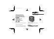
L53V2/XE (VCC-5775P) GB 2000, 7, 11 INSTRUCTION MANUAL BEDIENUNGSANLEITUNG MANUEL D’INSTRUCTIONS VCC-5775P COLOUR CCD camera CCD-Farbkamera Caméra CCD COULEUR CCD About this manual A propos de ce manuel Before installing and using the camera, please read this manual carefully. Be sure to keep it handy for later reference. Avant d’installer et d’utiliser la caméra, veuillez lire ce manuel attentivement. Gardez-le à portée de main pour toute référence ultérieure.
L53V2/XE (VCC-5775P) GB 2000, 7, 11 Depending on the conditions of use, installation and environment, please be sure to make the appropriate settings and adjustments. If you need help with installation and/or settings, please consult your dealer. English 1 CONTENTS PRECAUTIONS .............................. 3 PARTS NAMES .............................. 5 MOUNTING THE LENS.................. 7 CONNECTIONS.............................. 9 FLANGE-BACK ADJUSTMENT ...... 11 SETTINGS .............................
L53V2/XE (VCC-5775P) GB 2000, 7, 11 FEATURES • Built-in interline transfer method 1/3" CCD, approx. 470,000 picture elements • Low smear, anti-blooming, low lag, no • • • ENGLISH • • burning and no geometric distortion using the CCD solid state image device. 100% solid state components giving excellent immunity to shock and vibration Not subject to interference from magnetic or electrostatic fields High sensitivity, minimum required illumination is 1.4 lux (F1.
L53V2/XE (VCC-5775P) GB 2000, 7, 11 PRECAUTIONS In case of problem Do not use the camera if smoke or a strange odour comes from the unit, or if it seems not to function correctly. Disconnect the power cord immediately, and consult your dealer (or a Sanyo Authorized Service Centre). Do not open or modify Do not open the cabinet, as it may be dangerous and cause damage to the unit. For internal settings and repairs, consult your dealer (or a Sanyo Authorized Service Centre).
L53V2/XE (VCC-5775P) GB 2000, 7, 11 PRECAUTIONS Protect from high temperatures Do not install close to stoves, or other heat generating devices, such as spotlights, etc., or where it could be subject to direct sunlight, as that could cause deformation, discoloration or other damages. Be careful when installing close to the ceiling, in a kitchen or boiler room, as the temperature may raise to high levels. Install where the temperature range will stay between –10˚C and 50˚C.
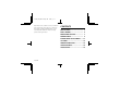
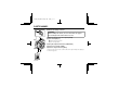
L53V2/XE (VCC-5775P) GB 2000, 7, 11 PARTS NAMES 1 Camera mounting screw hole 2 3 CAUTION: When installing the camera, select a location that can support the total weight of the camera and accessories.
L53V2/XE (VCC-5775P) GB 2000, 7, 11 PARTS NAMES 8 7 Flange-back lock screw 8 CS mount ring 9 Lens mount cap The cap is installed to protect the lens mount section. Remove the lens mount cap before installing a lens. 7 7 9 F Video output connector (VIDEO OUT: BNC type) Connect this connector to a device such as a VCR or monitor with a VIDEO IN connector.
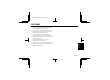
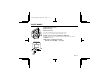
L53V2/XE (VCC-5775P) GB 2000, 7, 11 MOUNTING THE LENS Please use a DC type auto-iris lens (sold separately). Checking the lens mount Do not use lense with a length L more than 5 mm. If not, that may damage the camera and prevent proper installation. L 1 C mount type lens 1 2 2 Remove the lens mount cap from the camera. Install the auto-iris lens. CS mount type lens Carefully align the lens mount with the camera opening, then turn the lens slowly to install it.
L53V2/XE (VCC-5775P) GB 2000, 7, 11 MOUNTING THE LENS Rewiring the lens cable in the lens iris plug 1 1 Prepare the lens cable. Cut the cable at the plug, then remove approx. 8 mm of the cable sheath and strip about 2 mm from each wire. 2 2 Install the lens iris plug. Solder the cable to the pins following the correct pin layout (refer to the table and illustrations), then close the plug cover.
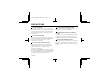
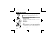
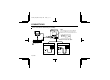
L53V2/XE (VCC-5775P) GB 2000, 7, 11 CONNECTIONS Basic connection for monitoring or recording Note: The polarities for the 24 V AC and the 12 V DC input connectors are indicated on the rating label found on the unit back panel. AC 24 V ~ ~ DC 12 V + – GND Push to insert the cable. (Video signal connections) : VIDEO IN : VIDEO OUT AC 24 V connection DC 12 V connection DC12V + – Fig. 1 English 9 Fig.
L53V2/XE (VCC-5775P) GB 2000, 7, 11 CONNECTIONS The peripheral devices (VCR, monitor, lens, etc.) and cables are sold separately. 1 Make the video signal connection between the camera and the monitor or timelapse VCR. 2 Power supply choices • Use a commercially available 24 V AC adaptor. Make sure to use a cable with an earth line (22AWG or more) to connect to the earth connector. (Fig.1.) • When using a DC 12 V power supply, make the connections as indicated in Fig. 2.
L53V2/XE (VCC-5775P) GB 2000, 7, 11 FLANGE-BACK ADJUSTMENT CS mount ring If the pick-up surface is not correctly positioned with relation to the lens focal point, the picture will be out of focus (in particular when using auto-iris power zoom lenses, sold separately). If that is the case, adjust the flange-back position as described below. 1 Before installing the lens, check that the two flange-back lock screws have been tightened.
L53V2/XE (VCC-5775P) GB 2000, 7, 11 SETTINGS Line phase adjustment When using a camera switcher to connect 2 cameras or more to one monitor, there may be a vertical roll of the images when switched. In such a case, set as described below. Set the Sync switch to the L-L position. Switch the display on the monitor from camera 1 to camera 2. Adjust the LINE PHASE volume on camera 2 until the vertical roll of the image stops. If more than two cameras are used, please repeat this procedure for all the cameras.
L53V2/XE (VCC-5775P) GB 2000, 7, 11 SETTINGS Lens iris adjustment If using a DC type auto-iris lens, you will need to set the LEVEL volume when shooting in the conditions described below. Counterclockwise: To decrease the brightness Clockwise: To increase the brightness • If shooting simultaneously in a dark room and through a bright window. • If the subject background is extremely bright or dark. • If the brightness of the picture on the monitor is not correct.
L53V2/XE (VCC-5775P) GB 2000, 7, 11 SETTINGS Under normal conditions, set the EI switch to the EI OFF position and use an auto-iris lens. However, if you have a manual lens or fixed iris lens, set the lens aperture to the shortest F stop and set the EI switch to the EI ON position. Note: Please refer to the specifications for dynamic range of the electronic iris. • If conditions are outside the electronic iris operation range or more than the maximum brightness, it will cause saturation of the CCD.
L53V2/XE (VCC-5775P) GB 2000, 7, 11 TROUBLESHOOTING Before taking the camera for repairs, please check below to make sure that the camera is used correctly. If it still does not perform correctly, please consult your dealer or a Sanyo Authorized Service Centre.
L53V2/XE (VCC-5775P) GB 2000, 7, 11 SPECIFICATIONS Scanning system: PAL standard (625 TV lines, 25 frames/sec.) Interlace: 2:1 interlace Image device: 1/3 inch solid state image device CCD Picture elements: 798 (H) x 584 (V) Effective picture elements: 753 (H) x 582 (V) Synchronizing system: Manual internal sync/ Line lock switching Resolution: 480 TV lines horizontally, 400 TV lines vertically Video output level: 1.
L53V2/XE (VCC-5775P) GB 2000, 7, 11 SPECIFICATIONS Dimensions: mm 51 63 (1) 68 Features and specifications are subject to change without prior notice or obligations.
L53V2/XE (VCC-5775P) GB 2000, 7, 11 ACCESSORIES 1 2 1C mount adaptor (5 mm) ........................1 pc. The C mount adaptor must be used to be able to install a C mount lens on the camera. 2Lens iris plug (4-pin).................................1 pc.
L53V2/XE (VCC-5775P) GB 2000, 7, 11 1AC6P1P2347-L53V2/XE(0700KP-DSP) Sanyo Electric Co, Ltd.