Proxima Desktop Projector 5500 User’s Guide Final 06/21/96
Warranty Proxima Corporation warrants that the Proxima®‚ Desktop Projector™ product manufactured by Proxima is free from defects in materials and workmanship under normal use during the Warranty Period. The Warranty Period commences on the day of purchase by the end-user. The Warranty Period is one year. The Projector lamp not covered by this Warranty. Each Proxima product is manufactured from new parts, or new and some used parts.
Contents Chapter 1 Your Proxima Desktop Projector 5500 What’s in the Box? ............................................................... 1-2 Quick Start ........................................................................... 1-3 Connector Panel .................................................................. 1-5 Control Panel ....................................................................... 1-6 Options and Accessories .....................................................
Chapter 4 Maintenance Cleaning the Lens ................................................................ 4-1 Replacing the Lamp ............................................................. 4-2 Cleaning the Air Filter ......................................................... 4-4 Changing the Remote Control’s Batteries .......................... 4-5 Chapter 5 Troubleshooting Where to get Help ................................................................ 5-1 Returning your DP5500 for Repair ..............
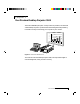
Chapter 1 Your Proxima Desktop Projector 5500 The Proxima® Desktop Projector™ family consists of portable, color data and video Desktop Projection™ products that make sharing data and presenting information as easy as connecting your computer to your monitor.
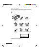
WHAT’S IN THE BOX? After you’ve opened the box and removed the DP5500 and accessory packs, make sure you have all of the items shown in Figure 1-2. S LOP LAMP TEMP CYC O ON STANDBY /ON INPUT MUTE ZOOM FOCUS MENU RESET CAUTION! The DP5500 should be treated like any other precision optical instrument. Handle it carefully.
QUICK START Place the DP5500 on a solid flat surface at a right angle (perpendicular) to the projection screen, parallel to the floor. Follow the appropriate section below for the type of system that you have. These steps are described in detail in Chapter 2. NOTE: The DP5500 has two sets of computer video and audio inputs. The following examples describe how to use INPUT 1. Desktop PCs 1 Unplug the monitor cable from the computer.
6 Turn the projector on and press the STANDBY/ON key. NOTE: If you turn the projector off while the computer is running, the external monitor will go blank. This is normal. Just turn the projector back on, and the monitor display will return. Notebooks NOTE: If you are connecting to an Apple PowerBook, attach the Mac - VGA cable adapter to the computer’s Video Out port (or video adapter cable).
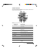
CONNECTOR PANEL All connections between the DP5500 and your computer or video source are made on the side connector panel. 2 3 S-VIDEO CYCLOPS 4 VIDEO L AUDIO R 1 1 5 2 AUDIO IN 11 AUDIO OUT 6 1 10 RGB OUT 7 2 RGB IN 9 CONTROL 8 Figure 1-3 The Connector Panel 1 CONNECTOR DESCRIPTION CYCLOPS Port Connects your computer to the Cyclops Interactive Pointer System. 2 S-VIDEO 1 & 2 Connects to an S-Video source.
CONTROL PANEL Use the DP5500’s control panel keys to turn the projector on or off, adjust the projected image, and to display and hide the menus. Power, warning, and alert lights give you important information about how your projector is working. ON P M DB AN ST N /O LA FUNCTION STANDBY/ON Turns the lamp on or off. INPUT Switches the video inputs. MUTE Turns the Audio on or off. ZOOM +/- Zooms in and out. FOCUS +/- Adjusts the focus. MENU Controls the menu.
Chapter 2 Setting Up the Desktop Projector 5500 YOUR DP5500 Before you begin, locate the main parts of the DP5500. 1 10 2 S OP CL CY O ON 9 DI AU T 0U O DI AU IN 3 T B OU RG L RO NT CO B IN RG 4 8 RIG RESEHT T DB Y STAN MENU + ZOOM – 5 FOCU S TIM ER VO L BLAN K SEAR 11 CH MU TE VID EO 6 1/2 RG B 1/2 INP UT 7 Figure 2-1 The Proxima DP5500 and Cyclops Remote Control 1. Control panel 7. Projection lens 2. Rear exhaust 8. Infrared lens 3.
GETTING STARTED Positioning the Projector Place the projector on a solid, flat surface at a right angle (perpendicular) to the projection screen and parallel to the floor. If you’re using a media cart, make sure the wheels are locked to prevent it from moving. ON LA MP TEM P MU INP UT ND STA /ON TE FO ZO OM RE ME CU S NU SE T BY Projection Screen Top View Perpendicular to the projection screen 8.
Transporting and Moving the Projector The projector has a recessed handle on one of the side panels. Always use the handle to transport it. The projector has protective feet on the side opposite the handle, as well as on the bottom. Figure 2-3 Transporting the projector If you are moving the projector a short distance, grasp it securely at the sides by the lower parts of the housing to support the weight of the unit.
Projector Cooling and Airflow The air intake grill is on the bottom of the projector. The air exhaust grill is on the rear panel. CAUTION! Never operate the projector if these grills are clogged or obstructed, or if the electric fans are not running.
CONNECTOR PANEL All connections between the projector and your computer or video source are made on the side connector panel. 2 3 S-VIDEO CYCLOPS 4 VIDEO L AUDIO R 1 1 5 2 AUDIO IN 11 AUDIO OUT 6 1 10 RGB OUT 7 2 RGB IN 9 CONTROL 8 Figure 2-6 The Connector Panel CONNECTOR 1 CYCLOPS Port DESCRIPTION Connects your computer to the Cyclops Interactive Pointer System. 2 S-VIDEO 1 & 2 Connects to an S-Video source.
CONNECTING POWER TO THE PROJECTOR The power cord receptacle and AC POWER switch are located below the projector’s connector panel. MONITOR OUT 2 RGB IN CONTROL Figure 2-7 Power receptacle and AC Power switch 1 Plug the appropriate power cord for your location into the power receptacle on the side of the projector. 2 Connect the power cord to a properly-grounded wall outlet. CONNECTING COMPUTER VIDEO Connecting a PC VGA VGA Use the included VGA video cable to connect your PC to the projector.
S-VIDEO CYCLOPS VIDEO AUDIO L R 1 2 AUDIO IN AUDIO OUT 1 MONITOR OUT 2 RGB IN CONTROL VGA Cable To Computer In From Monitor Out Figure 2-9 VGA connections 1 Unplug the monitor cable from the computer. 2 Plug one end of the supplied VGA cable into the RGB IN 1 port on the projector. Plug the other end of the VGA cable into the computer's Video Out (VGA) port. 3 Connect your audio source to the AUDIO IN 1 port on the projector (see page 2-10).
Connecting Macintosh Computers Use the video adapter cable shown below to connect a Macintosh computer to the DP5500. From Mac CPU To VGA Cable Mac – VGA Cable Adapter Figure 2-10 The Macintosh adapters Use the cable adapter and supplied VGA video cable to connect the projector to your Macintosh computer.
Use your existing monitor cable to connect the projector to a separate computer monitor, so you can use the projector and monitor at the same time. NOTE: The DP5500 only supports Multi-Sync monitors for Macintosh computers. Other monitors cannot be used. 5 Turn the projector on and press the STANDBY/ON key. NOTE: An external monitor is not required to use the DP5500. Connecting Notebook Computers Use the appropriate cable and adapter to connect your portable computer to the projector.
Special Configurations If your computer has an internal monitor but no external video capability (Macintosh Performa 575, PowerMac 5200, and certain PowerBooks), you need a separate video adapter card in order to attach the DP5500. Setup for a third-party adapter is identical to the procedures outlined in the Quick Start section in Chapter 1. Contact your dealer, Proxima Customer Service, or a third-party supplier for more information about an appropriate video adapter.
CONNECTING COMPOSITE VIDEO You can display composite video (NTSC, PAL or SECAM) on the DP5500. S-VIDEO CYCLOPS VIDEO L AUDIO R 1 2 Figure 2-14 Video 1 & 2 ports Use the supplied AV cable (see page 1-2) to connect an NTSC, PAL, or SECAM source to your projector. 1 Find the RCA connector on your video source marked Video Out (or something similar). This connector is usually yellow. Insert one of the AV cable’s yellow connectors into the Video Out jack on the video source.
3 Use the red and white AV Cable connectors to connect audio from the S-Video source to the projector. See connecting Non-Computer Audio, below. CONNECTING NON-COMPUTER AUDIO The AUDIO ports allow you to connect stereo or monaural audio from a composite video source. L AUDIO R Figure 2-16 Audio Input ports For stereo audio, use the supplied AV cable. 1 Insert the red (right) and white (left) ends of the cable into the Audio Out ports of a composite video’s audio source.
Connecting the PC to the Projector Through the CONTROL Port You can connect the projector to a computer through the CONTROL port. You can then use the joystick on your remote control as the computer's system mouse (see page 3-8). Before you begin, make sure that the projector and computer power is on and that the cables are securely connected. NOTE: This CONTROL feature is only available for PCs.
Projector Audio Out The projector contains an internal stereo system consisting of an amplifier and one speaker. Although this system provides high-quality audio output, a multimedia presentation may require independently powered stereo speakers or an external sound system. NOTE: Use the MUTE key to turn the projector’s internal and any connected external speakers on or off.
Chapter 3 Using the Desktop Projector 5500 TURNING ON THE PROJECTOR AND LAMP Power the DP5500 up before the computer. This allows the computer to sense the projector during its start-up sequence. Move the AC POWER switch to the ON position. The ON indicator on the projector control panel glows orange. The lamp is off when you first turn on the projector. Press the STANDBY/ON key on the operator panel for one second to turn the lamp on.
FOCUSING AND ZOOMING THE IMAGE You can use the title screen that appears when you first start the projector to make your focus and image size adjustments. 1 Press the ZOOM +/- key on the Control Panel or Remote Control to make the image larger (+) or smaller (-). NOTE: If you have a Cyclops interactive pointer system installed and you change the image size, you will have to recalibrate the Cyclops camera. 2 Adjust the focus using the FOCUS +/- buttons on the Control Panel or Remote Control.
CONTROL PANEL KEYS Use the DP5500’s control panel keys to turn the projector on or off, adjust the projected image, and to display and hide the menus. Power, warning, and alert lights give you important information about how your projector is working. FUNCTION STANDBY/ON Turns the lamp on or off. INPUT Switches between active connected video inputs. MUTE Turns the Audio on or off. ON KEY P M D AN ST N /O LA P M BY TE T PU IN ZOOM +/- Zooms in and out.
CONTROL PANEL INDICATORS Power, warning, and alert indicators give you important information about how your projector is working. FUNCTION ON Glows green if AC input and projector power ON INDICATOR P M DB AN ST N /O LA supplies are okay. Glows red if not, or if the air P M Y TE filter door is removed. IN Glows orange while in standby mode. PU T Flashes green during lamp start-up. E UT M Flashes orange during lamp cool-down.
TEMP The TEMP indicator illuminates if the projector overheats or if the air filter door on the bottom of the projector is open. A thermostat automatically turns off the power to the lamp until the projector cools. If an over-temperature condition occurs, perform the following checks while you allow the projector to cool: • Make sure that the room temperature is below 95° F (35° C). • Check the intake and exhaust vents. Clear any obstruction to the air flow. • Make sure that the fans are working.
USING THE REMOTE CONTROL The remote control contains all the key functions available on the DP5500 control panel, as well as several additional features. For best results, aim the remote control at the projection screen or at the projector’s front panel. Do not obstruct the red infrared eye located on the front of the projector.
KEY FUNCTION 1 JOYSTICK Functions as arrow keys or as a mouse. 2 RIGHT/RESET Resets the projector settings to the factory defaults if the menus are open. Functions as a right mouse button if the projector is in Host mode (see page 3-8). 3 MENU Displays or hides the menu. 4 FOCUS +/- Adjusts the focus. 5 VOLUME +/- Decreases or increases the volume of internal and/or external speakers. 6 MUTE Turns audio on or off. 7 RGB 1/2 Switches between connected computer sources.
USING THE JOYSTICK Use the joystick to move through the menus and select items or change values in them. You can also use the joystick as your system mouse if you install the serial cable and follow the boot instructions detailed in the Host Mode section (see below). • Move the joystick left or right to move across the menus. • Move the joystick up or down to move up or down in a menu. Move the joystick up to move up one level when you are at the top of a menu. • Press the joystick to make a menu selection.
3 Turn on the projector and light the lamp. 4 Turn on your computer. It should detect the projector as a serial mouse. 5 Use the joystick on the IR remote control to move the mouse. Notebook users may need to disable their integrated pointing device before using an external serial mouse. Consult your notebook's user’s guide for instructions on connecting a serial mouse. THE GRAPHICAL USER INTERFACE Your DP5500 graphical user interface makes it easy to control all of the projector’s functions.
USING THE MAIN MENU When you press MENU, the Main menu appears at the top of the screen. Figure 3-5 Main menu To turn the menu off, press MENU again. The menus will automatically disappear after a few seconds. The following table lists the main menu options that you can select. The Input and Image menus display only those items that are relevant to the selected input source (computer, video, or S-Video). MENU FUNCTION SETUP Adjusts image quality and position. INPUT Selects a video input source.
SETUP MENU The SETUP menu is used to adjust image quality and position. The selections are different for each type of video source. The computer source Setup menu is shown below. Figure 3-6 Setup Menu Screen OPTION WHAT IT DOES SOURCE VOLUME Increases or decreases the volume level. All sources BRIGHT Increases or decreases the intensity level All sources of the projected image. CONTRAST Adjusts the contrast in the projected image. All sources SHARPNESS Adjusts the sharpness of the image.
INPUT MENU Use the Input menu to select a video source. • Use the Arrow keys to select a source. • If you choose Video 1 or Video 2, select a video format. • Select Test Pattern to adjust the focus. Figure 3-7 Input menu MENU ITEM OPTIONS FUNCTION RGB 1 or 2 Selects the RGB 1 or 2 port. VIDEO 1 or 2 Selects the VIDEO 1 or 2 port and the video signal type: AUTO, NTSC, PAL, or SECAM. TEST PATTERN 3-12 Chapter Three Displays a full-screen test pattern.
IMAGE MENU This menu is used to adjust the projected video image and select how the projector will display. Figure 3-8 Image menu MENU ITEM MIRROR OPTIONS FUNCTION Standard operating mode. Flips the picture horizontally, vertically, or horizontally and vertically. BLANK Selects a blank color (white, blue, or black). REVEAL Selects the speed for revealing an image. MENU SIZE Changes the on-screen menu size. MESSAGE Turn the on-screen image source messages on or off.
OPTION (OPT.) MENU The OPT menu is used to control the projector’s communications settings.
MENU ITEM COMM SPEED OPTIONS FUNCTION Selects the speed of data transmission. COM. BITS Selects the format of data transmission: Use 7N1 for 7 data-bits, No parity, 1 stop bit. Use 8N1 for 8 data-bits, No parity, 1 stop bit. MOUSE Selects the speed of mouse movement. TIMER Sets the duration of the Break Timer. LANGUAGE Sets the language for the menu displays. AUTO OFF Sets the time the projector can run with no action before it will automatically turn off. The maximum is 99.
Setting the Timer You can set the Timer to count down for breaks, class activities, and other presentation requirements. 1 From the Options menu, choose Timer and press the right MENU key on the control panel or move the joystick to the right. 2 When the Timer menu appears, use the MENU keys on the control panel or the joystick on the remote control to set the time. 3 Press TIMER on the remote control, and the clock will begin to count down.
Chapter 4 Maintenance There is very little involved with the care and maintenance of your DP5500. However, common sense and periodic maintenance will ensure top performance. The lamp, lenses, mirrors, and LCD panels have been carefully aligned at the factory to give you the clearest, brightest image possible. However, physical abuse can cause misalignment or damage to the optical elements. Be careful when you use or handle any of the optical elements.
REPLACING THE LAMP 1 Turn off the projector. 2 Unplug the projector’s power cord from the wall socket and remove it from the projector’s power receptacle. 3 Remove the screw on the right side of the rear panel and remove the service door. Figure 4-1 Removing the service door 4 Unscrew the four lamp assembly screws (they will not come out of the lamp assembly).
CAUTION! The lamp assembly gets very hot during operation. Use appropriate care when changing lamps. Make sure that the lamp assembly has cooled for at least three to five minutes before touching it. 5 Grasp the rear of the lamp assembly and firmly pull the assembly out. Figure 4-3 Removing the lamp assembly 6 Replace the old lamp assembly with a new one, carefully aligning the power pins on the bottom, and pressing it firmly into place.
CLEANING THE AIR FILTER You should change or clean the air intake filter after every 250 operating hours to maintain proper cooling. This filter is located on the bottom of the projector, under the grill. 1 Disconnect all cables and cords from the projector. 2 Turn the projector on its side, connector panel down. 3 Remove both screws on the filter cover.
5 After you have disassembled it, clean the air filter using a vacuum cleaner. If it is still dirty, wipe the air filter with a moist cloth, then wipe it with a dry cloth. Figure 4-6 The components of the air filter 6 Reassemble and reinstall the air filter. CHANGING THE REMOTE CONTROL’S BATTERIES If the remote control is not going to be used for awhile, remove the batteries from the unit. If the remote control does not appear to be working properly, replace the batteries.
Chapter 5 Troubleshooting WHERE TO GET HELP If you need help: 1 Check the Troubleshooting Chart. 2 Call your dealer’s technical support line and explain your problem. 3 Call Proxima at: USA. and Canada: (619) 457-5500. Press 1 for Customer Service. (619) 457-8542 (Fax) Outside USA and Canada: (619) 457-5500. Press 1 for Customer Service. (619) 622-0173 (Fax) Europe: +31-43-358 5200 +31-43-358 5201 (Fax) Internet (WorldWide Web) http://www.prxm.com (Click Customer Service.
Projector PROBLEM LIKELY CAUSE POSSIBLE SOLUTION(S) No image projected No power to projector. Turn power ON. Check AC cord. Check power to electrical outlet. Lamp not on. Turn lamp ON. Lamp burned out. Replace lamp assembly. Over temperature indication. Allow projector to cool; turn projector OFF and then ON. Make sure the bottom air filter door is closed. No computer image Loose cable. projected Check and secure cable connections. No power to computer. Incompatible video system.
PROBLEM LIKELY CAUSE Projected image Zoom lens not adjusted Adjust zoom lens or move smaller than screen properly, or projector too projector away from screen close to screen. screen. H. or V. POSIT adjusted Adjust H. and/or V. POSIT; if incorrectly. image will not center, check for Image off-center POSSIBLE SOLUTION(S) compatibility problems. Compatibility problem. Verify projector is image compatible with one of the standards listed in Appendix A.
PROBLEM LIKELY CAUSE POSSIBLE SOLUTION(S) Getting excessive CONTRAST setting is Adjust CONTRAST setting, then white or washout too high. in NTSC, PAL, or adjust BRIGHT (brightness) setting. S-VHS mode No audio Audio source(s). Check audio source(s) for power ON and proper operation. Loose/improper cable. Check and secure cabling between audio source(s) and projector. TEMP Air vent(s) clogged.
RETURNING YOUR DP5500 FOR REPAIR If the DP5500 or any of its accessories are determined to be defective: 1 Contact Proxima Customer Service to request a Return Material Authorization (RMA) number.
Appendix A Specifications DP5500 SPECIFICATIONS Color 16.7 million colors Display 3 polysilicon liquid crystal panels Compatibility NTSC, PAL, SECAM, and S-VHS Projection Lamp 250 Watt, metal-halide lamp Optics Zoom lens F3.0 ~ 3.8 f46.5 ~ 74.4mm Keystone Correction 8.
Appendix B Accessories and Replacement Parts REPLACEMENT PARTS PART PART NUMBER Lamp Assembly L84 Remote Control A15 Power Cord - US C151-10 Power Cord - Europe C152-10 VGA Video Cable C950-06 VGA - Mac Cable Adapter C951 S-Video Cable C552-6 AV Cable C550-6 Serial Cable C551-6 Mini-stereo to Mini-stereo Cable 900-55010 Lens Cap 280-00099 Air Filter 280-00153 OPTIONAL ACCESSORIES OPTION MODEL / PART NUMBER Rolling Hard Case A295 Rolling Soft Case A298 Cyclops Interactive Poi
Index A G AC Power switch 2-6 Accessories B-1 AUDIO 1-5, 2-5 AUDIO OUT 1-5, 2-5 Audio Out Ports 2-14 External Speaker System Connection 2-14 External Stereo System Connection 2-14 Audio Ports Monaural Source 2-12 Stereo Source 2-12 Getting Started 2-2 Graphical User Interface 3-8 C L Circuit Breaker Reset switch 2-6 Computer Audio Port Connecting a Monaural Source 2-10 Connecting a Stereo Source 2-10 Computer Video Connection Macintosh Computers 2-8 Notebook Computers 2-9 PC 2-6 Special Configurations