
Service manual


33
CP-SX1350(P5SX+)
#6607
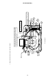
Fan for the red
colored panel
Attach with the optical
unit assembly.
Attach with the optical
unit assembly.
Attach with the optical
unit assembly.
A83
Left speaker
CNRM
Signal board
Fan for the blue colored panel
CNME
#6606
After connecting the
CNME cable to the EY01
connectors for the dust
sensor board, attach it to
the optical unit.
#6604
Fan for the green
colored panel
CNLS
CNLS
Make sure to not tangle the cables when mounting the optical unit.
2. Wiring of the optical unit when it is mounted to the bottom case
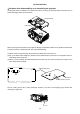
Connect the CNRM cables to the ER01
remote control's connectors.
* Attach the remote control
board, the clasps and cover
as per the assembly diagram.
TAP2
Pull the CNLS cables to the rear so that they do not get caught
in the gear cogs, after using the TAP2 to clasp them underneath
the lens.
Connect the CNLS cables to the connectors that are besides the lens.
Pass them underneath the lens as depicted in the diagram at right.
They need to be configured so that they do not catch on the lens or the
motor's gears.
Connect the cable end that is closest to its binding Tapes to the
connector beside the lens.
Do not stress the flexible cable for the lens
when wiring the CNLS cable.
TAP2
FRONT VIEW
Lens
#680
Lamp fan
Protruding part
Cover the protruding
portion of the clasp
with tape.
(As per the assembly
diagram.)
Pass the CNLC cable
underneath the protruding part
of the clasp as depicted in the
diagram to prevent the switch
lever cable from becoming enclosed.
CNLS
Clasp underneath
the lens
Install the switchboard in the clasp in the optical unit assembly.
The optical unit may be installed with CNLC cable connected to
the E941 connector.
Lever
Attach with the optical
unit assembly.
Wiring diagram 3
Attach TAP 2, after configuring the cable in the
approximate center of the clasp underneath the lens.
(So that the gears of the motor do not catch, make
sure that they do not get caught on the base of the
lens when the lens is shifted downward.)
Make sure that the CNLS connector is
connected firmly and straightly to the
connector beside the lens, after attaching
TAP2.
CNLC