
Installation and Operation Guide

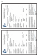
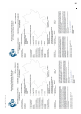
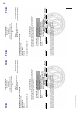
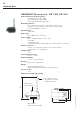
Table Of Contents
- Chapter 1: Introduction
- 1.1 First steps
- 1.2 Service addresses
- 1.3 About this manual
- Chapter 2: Safety
- 2.1 Safety symbols
- 2.2 Information for the system operator
- 2.3 Information for operating personnel
- 2.4 Intended use
- 2.5 Residual risks and safety measures
- Declaration of conformity
- Certifications
- Chapter 3: Technical data
- Chapter 4: System description
- 4.1 VIBCONNECT RF bridge
- 4.2 VIBCONNECT RF sensor unit
- 4.3 VIBCONNECT RF sensor
- Chapter 5: Installation & commissioning
- 5.1 Quick guide
- 5.2 Configuration in OMNITREND
- 5.3 Installation & commissioning of bridge
- 5.4 Installation & commissioning of sensor unit
- 5.5 Installation of sensors
- 5.6 Configuration in OMNITREND (continued)
- 5.7 Installing additional sensor unit
- Chapter 6: Maintenance
- 6.1 Cleaning
- 6.2 System time correction
- 6.3 Installation report
- 6.4 Battery-powered sensor unit
- 6.5 Update
- 6.6 Warranty
- 6.7 Spare parts and accessories
- Chapter 7: Troubleshooting
- Chapter 8: After use

11
VIBCONNECT RF 05.2012
Safety
Note
Risk of damage to equipment while housing is open!
Touching the electronic components on the mother board can lead
to electrostatic discharge, which can damage system components.
» If contact with such components cannot be excluded, wear an
earthing wristband.
Note
EMC
High-frequency radiation and electrostatic discharge (ESC) near
the sensors can lead to incorrect measurements.
» Do not install sensor cables in high-voltage cable ducts.
Note
Radio approval
The antennas on the system components are installed at the fac-
tory and must not be removed.
» Contact PRÜFTECHNIK, if you want to use a different type of
antenna or if you need to extend the original antenna from an
enclosure with an antenna cable.