
Installation and Operation Guide
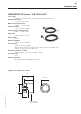
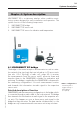
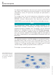
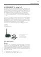
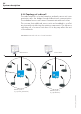
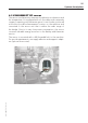
Table Of Contents
- Chapter 1: Introduction
- 1.1 First steps
- 1.2 Service addresses
- 1.3 About this manual
- Chapter 2: Safety
- 2.1 Safety symbols
- 2.2 Information for the system operator
- 2.3 Information for operating personnel
- 2.4 Intended use
- 2.5 Residual risks and safety measures
- Declaration of conformity
- Certifications
- Chapter 3: Technical data
- Chapter 4: System description
- 4.1 VIBCONNECT RF bridge
- 4.2 VIBCONNECT RF sensor unit
- 4.3 VIBCONNECT RF sensor
- Chapter 5: Installation & commissioning
- 5.1 Quick guide
- 5.2 Configuration in OMNITREND
- 5.3 Installation & commissioning of bridge
- 5.4 Installation & commissioning of sensor unit
- 5.5 Installation of sensors
- 5.6 Configuration in OMNITREND (continued)
- 5.7 Installing additional sensor unit
- Chapter 6: Maintenance
- 6.1 Cleaning
- 6.2 System time correction
- 6.3 Installation report
- 6.4 Battery-powered sensor unit
- 6.5 Update
- 6.6 Warranty
- 6.7 Spare parts and accessories
- Chapter 7: Troubleshooting
- Chapter 8: After use

19
VIBCONNECT RF 05.2012
size 19
23
19
19
6
Name plate
(laser marked)
VIBCONNECT RF Sensor – VIB 7.205-2,9EX
Sensor type
Vibration acceleration sensor with integrated temperature sensor
Transmission factor
3.5 mV / ms
-2
(± 10 %)
Max. measurement range
500 ms
-2
r.m.s. (± 10 %)
Frequency range
5 Hz ... 10 kHz (± 3 dB)
Temperature measuring range
-40°C ... +85°C (± 3°C)
Cable type
4-wire cable incl. shield
Cable length
2.9 m
Relative humidity
< 95 %, non-condensing
Case material
Stainless steel VA 1.4305 /
Grivory HTV (resistant amongst others to diesel, crude oil, hydraulic and
engine oil, lubricants, tar, turpentine)
Chemical resistance of cable
Acids, alkalines, oils, fuels: very high resistance
Protection class
IP 65
Fixture to machine
Mounting adapter with UNF 1/4" thread
Technical data
Original size, dimensions in mm