
Installation and Operation Guide
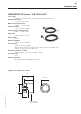
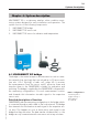
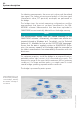
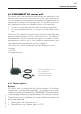
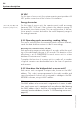
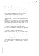
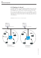
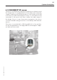
Table Of Contents
- Chapter 1: Introduction
- 1.1 First steps
- 1.2 Service addresses
- 1.3 About this manual
- Chapter 2: Safety
- 2.1 Safety symbols
- 2.2 Information for the system operator
- 2.3 Information for operating personnel
- 2.4 Intended use
- 2.5 Residual risks and safety measures
- Declaration of conformity
- Certifications
- Chapter 3: Technical data
- Chapter 4: System description
- 4.1 VIBCONNECT RF bridge
- 4.2 VIBCONNECT RF sensor unit
- 4.3 VIBCONNECT RF sensor
- Chapter 5: Installation & commissioning
- 5.1 Quick guide
- 5.2 Configuration in OMNITREND
- 5.3 Installation & commissioning of bridge
- 5.4 Installation & commissioning of sensor unit
- 5.5 Installation of sensors
- 5.6 Configuration in OMNITREND (continued)
- 5.7 Installing additional sensor unit
- Chapter 6: Maintenance
- 6.1 Cleaning
- 6.2 System time correction
- 6.3 Installation report
- 6.4 Battery-powered sensor unit
- 6.5 Update
- 6.6 Warranty
- 6.7 Spare parts and accessories
- Chapter 7: Troubleshooting
- Chapter 8: After use

22
VIBCONNECT RF 05.2012
System description
For vibration measurements, the sensor unit only records the related
time signal. The further processing and analysis of the time signal
(characteristic value, FFT spectrum, envelopes) are performed on
the bridge.
The bridge stores the actual measuring configurations and the
measurements that have not yet been transferred to the OM-
NITREND software. Measurements that have been uploaded to
OMNITREND are automatically deleted from the bridge memory.
Note
The measurement import must be started manually in the
OMNITREND software. Alternatively, the import can also be au-
tomated through a Windows task. For details, see the Technical
Release # 21, available for free on the PRÜFTECHNIK homepage.
Ensure that the data is regularly written to OMNITREND. Other-
wise, the memory capacity of the bridge might be exceeded so
the oldest measurements are automatically overwritten with the
latest ones.
For optimum reception, install the bridge in an exposed location,
preferably within sight contact of all connected sensor units. The
transmission range in the open field is maximum 300 m (optimum
conditions). For larger machine parks, you might need to install
several bridges operating separate wireless networks.
The bridge is powered by mains power.
Large industrial sites can
be serviced by installing
several bridges, whereby
the number of bridges is
not limited.