
Installation and Operation Guide
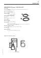
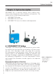
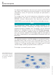
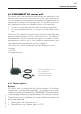
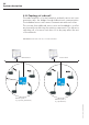
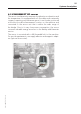
Table Of Contents
- Chapter 1: Introduction
- 1.1 First steps
- 1.2 Service addresses
- 1.3 About this manual
- Chapter 2: Safety
- 2.1 Safety symbols
- 2.2 Information for the system operator
- 2.3 Information for operating personnel
- 2.4 Intended use
- 2.5 Residual risks and safety measures
- Declaration of conformity
- Certifications
- Chapter 3: Technical data
- Chapter 4: System description
- 4.1 VIBCONNECT RF bridge
- 4.2 VIBCONNECT RF sensor unit
- 4.3 VIBCONNECT RF sensor
- Chapter 5: Installation & commissioning
- 5.1 Quick guide
- 5.2 Configuration in OMNITREND
- 5.3 Installation & commissioning of bridge
- 5.4 Installation & commissioning of sensor unit
- 5.5 Installation of sensors
- 5.6 Configuration in OMNITREND (continued)
- 5.7 Installing additional sensor unit
- Chapter 6: Maintenance
- 6.1 Cleaning
- 6.2 System time correction
- 6.3 Installation report
- 6.4 Battery-powered sensor unit
- 6.5 Update
- 6.6 Warranty
- 6.7 Spare parts and accessories
- Chapter 7: Troubleshooting
- Chapter 8: After use

26
VIBCONNECT RF 05.2012
4.2.4 Topology of radio cell
The radio network is of a star formation, and each sensor unit com-
municates with the bridge through bidirectional communication.
The individual sensor units cannot communicate with each other.
This ensures that additional sensor units can be added to a cell at
any time without affecting the existing components. The failure or
switching off of a sensor unit does not in any way affect the rest
of the network.
System description
Maintenance Control desk
Ethernet
VIBCONNECT RF radio cells are of a star formation.
max. 300 m
Machine park 1
(e.g. power generation)
Machine park 2
(e.g. production)