
Installation and Operation Guide
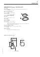
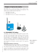
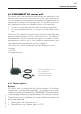
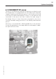
Table Of Contents
- Chapter 1: Introduction
- 1.1 First steps
- 1.2 Service addresses
- 1.3 About this manual
- Chapter 2: Safety
- 2.1 Safety symbols
- 2.2 Information for the system operator
- 2.3 Information for operating personnel
- 2.4 Intended use
- 2.5 Residual risks and safety measures
- Declaration of conformity
- Certifications
- Chapter 3: Technical data
- Chapter 4: System description
- 4.1 VIBCONNECT RF bridge
- 4.2 VIBCONNECT RF sensor unit
- 4.3 VIBCONNECT RF sensor
- Chapter 5: Installation & commissioning
- 5.1 Quick guide
- 5.2 Configuration in OMNITREND
- 5.3 Installation & commissioning of bridge
- 5.4 Installation & commissioning of sensor unit
- 5.5 Installation of sensors
- 5.6 Configuration in OMNITREND (continued)
- 5.7 Installing additional sensor unit
- Chapter 6: Maintenance
- 6.1 Cleaning
- 6.2 System time correction
- 6.3 Installation report
- 6.4 Battery-powered sensor unit
- 6.5 Update
- 6.6 Warranty
- 6.7 Spare parts and accessories
- Chapter 7: Troubleshooting
- Chapter 8: After use

27
VIBCONNECT RF 05.2012
4.3 VIBCONNECT RF sensor
The sensor simultaneously measures the vibration acceleration and
the temperature. It is equipped with a 2.9 m cable and is extremely
compact, requiring only minimum space. It can thus be positioned
at the best possible measurement location on the machine and
connected to the sensor unit that is within the radio range of
the bridge. Due to its very low power consumption, the sensor
conserves valuable energy resources in the Battery and Harvester
version.
The sensor is mounted with a M8 threaded bolt to the machine.
For special requirements, we supply adhesive and magnetic adapt-
ers (optional accessories).
System description