
Installation and Operation Guide
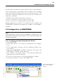
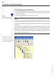
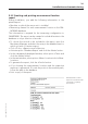

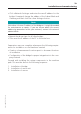
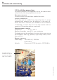

Table Of Contents
- Chapter 1: Introduction
- 1.1 First steps
- 1.2 Service addresses
- 1.3 About this manual
- Chapter 2: Safety
- 2.1 Safety symbols
- 2.2 Information for the system operator
- 2.3 Information for operating personnel
- 2.4 Intended use
- 2.5 Residual risks and safety measures
- Declaration of conformity
- Certifications
- Chapter 3: Technical data
- Chapter 4: System description
- 4.1 VIBCONNECT RF bridge
- 4.2 VIBCONNECT RF sensor unit
- 4.3 VIBCONNECT RF sensor
- Chapter 5: Installation & commissioning
- 5.1 Quick guide
- 5.2 Configuration in OMNITREND
- 5.3 Installation & commissioning of bridge
- 5.4 Installation & commissioning of sensor unit
- 5.5 Installation of sensors
- 5.6 Configuration in OMNITREND (continued)
- 5.7 Installing additional sensor unit
- Chapter 6: Maintenance
- 6.1 Cleaning
- 6.2 System time correction
- 6.3 Installation report
- 6.4 Battery-powered sensor unit
- 6.5 Update
- 6.6 Warranty
- 6.7 Spare parts and accessories
- Chapter 7: Troubleshooting
- Chapter 8: After use

31
VIBCONNECT RF 05.2012
5.2.3 Creating and printing measurement location
report
During installation, you add the following information to the
printed report:
• Machine on which the sensor unit is installed
• Measuring channel for each measurement location in the OM-
NITREND database
This information is required for the measuring configuration in
OMNITREND. The report can be created to include all entries in the
database or only a selection of records.
• To choose the records to be included in the report, open the
Machinery Manager, and select the entry in the database tree for
which you wish to create a report.
• Click <Tools>, <Reports> and <Selector>.
• Activate option ‘Database Report’ and click the <Next> button.
• In the subsequently displayed window, select option <Tree> and
click the <Next> button.
• In the next window, select options <Meas. Location info> /<Meas.
location>.
• To generate the report, click the <Finish> button.
• A list showing the measurement locations and the respective
machines is generated. To locate the points in the machine park,
follow the path in the database.
• Print a copy of the report.
Installation and commissioning
Measurement location
report for a machine train
consisting of a pump
and a motor.