
Installation and Operation Guide
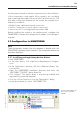

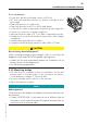

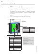
Table Of Contents
- Chapter 1: Introduction
- 1.1 First steps
- 1.2 Service addresses
- 1.3 About this manual
- Chapter 2: Safety
- 2.1 Safety symbols
- 2.2 Information for the system operator
- 2.3 Information for operating personnel
- 2.4 Intended use
- 2.5 Residual risks and safety measures
- Declaration of conformity
- Certifications
- Chapter 3: Technical data
- Chapter 4: System description
- 4.1 VIBCONNECT RF bridge
- 4.2 VIBCONNECT RF sensor unit
- 4.3 VIBCONNECT RF sensor
- Chapter 5: Installation & commissioning
- 5.1 Quick guide
- 5.2 Configuration in OMNITREND
- 5.3 Installation & commissioning of bridge
- 5.4 Installation & commissioning of sensor unit
- 5.5 Installation of sensors
- 5.6 Configuration in OMNITREND (continued)
- 5.7 Installing additional sensor unit
- Chapter 6: Maintenance
- 6.1 Cleaning
- 6.2 System time correction
- 6.3 Installation report
- 6.4 Battery-powered sensor unit
- 6.5 Update
- 6.6 Warranty
- 6.7 Spare parts and accessories
- Chapter 7: Troubleshooting
- Chapter 8: After use

36
VIBCONNECT RF 05.2012
5.3.4 Connecting bridge
CAUTION
Risk of injury from electric shock!
When connecting the bridge to the power supply without taking
the necessary safety precautions, there is a risk of energy from
high voltage (220 V).
» The electrical connection must be established by a qualified
electrician.
» The mains voltage must conform to the IEC guidelines.
» An external interface (fuse or switch) must be provided in order
to disconnect the power supply securely.
» Before carrying out any installation, repair or maintenance work
on the bridge, disconnect it from the power supply.
Note
Risk of damage to equipment while housing is open!
Touching the electronic components on the mother board can lead
to electrostatic discharge, which can damage system components.
» If contact with such components cannot be excluded, wear an
earthing wristband.
• Remove the dummy plugs from the cable entries.
Network Cable
• Feed the network cable through the left gland.
• Drag one of the enclosed ferrite sleeves over the cable end.
• Connect the bridge to the data network (see also '5.3.6 Over-
view of connections and interfaces', page 38).
Installation and commissioning