
Installation and Operation Guide
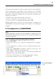
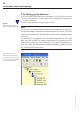

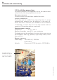
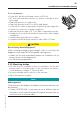
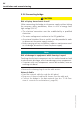

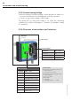
Table Of Contents
- Chapter 1: Introduction
- 1.1 First steps
- 1.2 Service addresses
- 1.3 About this manual
- Chapter 2: Safety
- 2.1 Safety symbols
- 2.2 Information for the system operator
- 2.3 Information for operating personnel
- 2.4 Intended use
- 2.5 Residual risks and safety measures
- Declaration of conformity
- Certifications
- Chapter 3: Technical data
- Chapter 4: System description
- 4.1 VIBCONNECT RF bridge
- 4.2 VIBCONNECT RF sensor unit
- 4.3 VIBCONNECT RF sensor
- Chapter 5: Installation & commissioning
- 5.1 Quick guide
- 5.2 Configuration in OMNITREND
- 5.3 Installation & commissioning of bridge
- 5.4 Installation & commissioning of sensor unit
- 5.5 Installation of sensors
- 5.6 Configuration in OMNITREND (continued)
- 5.7 Installing additional sensor unit
- Chapter 6: Maintenance
- 6.1 Cleaning
- 6.2 System time correction
- 6.3 Installation report
- 6.4 Battery-powered sensor unit
- 6.5 Update
- 6.6 Warranty
- 6.7 Spare parts and accessories
- Chapter 7: Troubleshooting
- Chapter 8: After use

38
VIBCONNECT RF 05.2012
Antenna
(section)
Power supply
Technical data
Terminal strip for network connection:
• Crimp terminals
• Cross-section: < 5 mm²
Terminal strip on power supply and PE:
• Screw terminals
• Size: < 1.5 mm²
Cable glands
• Size: M16
• Clamping range: 5 ... 10 mm
Terminal Wire colour
N: Neutral blue
L: Phase brown or black
PE: Protective earth green / yellow
EIA-TIA 568A
Terminal Wire colour
1 WH-GN (white / green)
2 GN (green)
3 WH-OG (white / orange)
4 BU (blue)
5 WH-BU (white-blue)
6 OG (orange)
7 WH-BN (white / brown)
8 BN (brown)
5.3.5 Commissioning bridge
• Before commissioning the bridge, check whether all cable con-
nections and fixtures of the bridge are correctly executed.
• Switch on the power supply of the bridge.
The green LED on the power supply is on. After the operating
software has fully booted (approx. 1 minute), the bridge is ready
for operation.
5.3.6 Overview of connections and interfaces
Installation and commissioning
Reset key