
Installation and Operation Guide

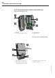

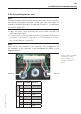
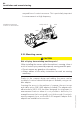
Table Of Contents
- Chapter 1: Introduction
- 1.1 First steps
- 1.2 Service addresses
- 1.3 About this manual
- Chapter 2: Safety
- 2.1 Safety symbols
- 2.2 Information for the system operator
- 2.3 Information for operating personnel
- 2.4 Intended use
- 2.5 Residual risks and safety measures
- Declaration of conformity
- Certifications
- Chapter 3: Technical data
- Chapter 4: System description
- 4.1 VIBCONNECT RF bridge
- 4.2 VIBCONNECT RF sensor unit
- 4.3 VIBCONNECT RF sensor
- Chapter 5: Installation & commissioning
- 5.1 Quick guide
- 5.2 Configuration in OMNITREND
- 5.3 Installation & commissioning of bridge
- 5.4 Installation & commissioning of sensor unit
- 5.5 Installation of sensors
- 5.6 Configuration in OMNITREND (continued)
- 5.7 Installing additional sensor unit
- Chapter 6: Maintenance
- 6.1 Cleaning
- 6.2 System time correction
- 6.3 Installation report
- 6.4 Battery-powered sensor unit
- 6.5 Update
- 6.6 Warranty
- 6.7 Spare parts and accessories
- Chapter 7: Troubleshooting
- Chapter 8: After use

39
VIBCONNECT RF 05.2012
Installation and commissioning
5.4 Installation & commissioning of sensor
unit
The operator of the system must ensure that the following condi-
tions are met and all necessary preparations are completed.
location of installation
• The sensor unit must be mounted on or near the machine.
Choose a suitable position on the machine that is only exposed
to low vibration. Alternatively, provide a suitable holder for the
sensor unit.
• Ensure that the location of installation has good radio reception.
Measure the reception field strength at several, potentially suit-
able installation points (see “Measuring reception field strength
at location of installation”, page 38).
• The distance between the measurement location and the sensor
unit can be bridged with the 2.9 m sensor cable; before mount-
ing the sensor unit and the sensors, ensure that they are not
more than 2.9 m apart.
Permissible ambient conditions
Temperature range for sensor unit: – 25 °C to +80 °C
Relative air humidity: max. 95 %, non-condensing
The sensor unit must not be installed in a location that is near
a strong electromagnetic field (e.g. generator, high-voltage cable,
electric drive unit, etc.).
required connections / batteries:
• 24 V DC for sensor units with permanent power supply
• 3.6 V lithium batteries, size C; Two batteries per sensor unit
tools and materials
• Power drill, drill bit and thread cutter for M5 bolts
• M5 bolts and matching washers for fixture of sensor unit (2 bolts
per sensor unit)
• Open-end spanner of suitable size
• Ferrules for connection of sensor line
• Standard tools for electrical installation (wire cutter, cable stripper,
screwdriver)
• Suitable strain relief devices for cables
• If required: WLAN antenna extension cable (SMA)
For 24V sensor unit:
• 3-wire electric power cable for power supply line
• Ferrules for connection of power supply line