
Installation and Operation Guide

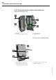

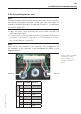
Table Of Contents
- Chapter 1: Introduction
- 1.1 First steps
- 1.2 Service addresses
- 1.3 About this manual
- Chapter 2: Safety
- 2.1 Safety symbols
- 2.2 Information for the system operator
- 2.3 Information for operating personnel
- 2.4 Intended use
- 2.5 Residual risks and safety measures
- Declaration of conformity
- Certifications
- Chapter 3: Technical data
- Chapter 4: System description
- 4.1 VIBCONNECT RF bridge
- 4.2 VIBCONNECT RF sensor unit
- 4.3 VIBCONNECT RF sensor
- Chapter 5: Installation & commissioning
- 5.1 Quick guide
- 5.2 Configuration in OMNITREND
- 5.3 Installation & commissioning of bridge
- 5.4 Installation & commissioning of sensor unit
- 5.5 Installation of sensors
- 5.6 Configuration in OMNITREND (continued)
- 5.7 Installing additional sensor unit
- Chapter 6: Maintenance
- 6.1 Cleaning
- 6.2 System time correction
- 6.3 Installation report
- 6.4 Battery-powered sensor unit
- 6.5 Update
- 6.6 Warranty
- 6.7 Spare parts and accessories
- Chapter 7: Troubleshooting
- Chapter 8: After use

41
VIBCONNECT RF 05.2012
Installation and commissioning
Technical data
Terminal strip:
• Crimp terminals
• Cross-section: < 0.5 mm²
Cable glands
• Size: M6 (sensor line)
• Clamping range: 2 ... 3.2 mm
• Size: M8 (24 V / harvester)
• Clamping range: 3 ... 5 mm
Terminal strip: sensor / power supply
Terminal Function
Sensor 1
1 5 VDC power supply (red wire)
2 Vibration signal (white wire)
3 Temperature signal (black wire)
4 Shield earthing line, GND
Energy harvester / commissioning
5 Short-circuit bridge (commissioning)
6 Short-circuit bridge (commissioning)
7 +8 V (energy harvester)
8 GND (energy harvester)
9 7– 9 V (external power supply)
10 GND (external power supply)
11 Reception field strength (0..1.25 V)
12 Reception field strength (0..1.25 V)
Sensor 2
13 5 VDC power supply (red wire)
14 Vibration signal (white wire)
15 Temperature signal (black wire)
16 Shield earthing line, GND
17 Blind terminal, no function
Additional terminal strip,
24V version
Terminal Function
Power supply
1
-
2
24 V
3
GND
4
-
Terminal strips and LEDs in sensor unit
LEDs in sensor unit:
• GREEN: Data transmission
• YELLOW: Measurement
• RED: Data transmission error
Terminal 1
Power supply
(24 V version)
Terminal 1
Terminal 17