
Installation and Operation Guide

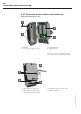

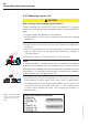
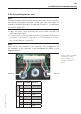
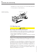
Table Of Contents
- Chapter 1: Introduction
- 1.1 First steps
- 1.2 Service addresses
- 1.3 About this manual
- Chapter 2: Safety
- 2.1 Safety symbols
- 2.2 Information for the system operator
- 2.3 Information for operating personnel
- 2.4 Intended use
- 2.5 Residual risks and safety measures
- Declaration of conformity
- Certifications
- Chapter 3: Technical data
- Chapter 4: System description
- 4.1 VIBCONNECT RF bridge
- 4.2 VIBCONNECT RF sensor unit
- 4.3 VIBCONNECT RF sensor
- Chapter 5: Installation & commissioning
- 5.1 Quick guide
- 5.2 Configuration in OMNITREND
- 5.3 Installation & commissioning of bridge
- 5.4 Installation & commissioning of sensor unit
- 5.5 Installation of sensors
- 5.6 Configuration in OMNITREND (continued)
- 5.7 Installing additional sensor unit
- Chapter 6: Maintenance
- 6.1 Cleaning
- 6.2 System time correction
- 6.3 Installation report
- 6.4 Battery-powered sensor unit
- 6.5 Update
- 6.6 Warranty
- 6.7 Spare parts and accessories
- Chapter 7: Troubleshooting
- Chapter 8: After use

45
VIBCONNECT RF 05.2012
Installation and commissioning
5.4.4 Connecting sensor unit
Note
The sensor cables must only be connected to the sensor unit after
the sensors have been installed, so that you have the option to
extend or shorten the cables if required (see also '5.5 Installation
of sensors', page 47).
• Open the sensor unit and feed the sensor cable through the
cable gland provided.
• Connect the four tinned cable strands to the respective terminals
for sensor 1 and sensor 2 (see also '5.4.1 Overview of connec-
tions and interfaces', page 40).
Note
Each sensor can measure two channels. The assignment of
the channels to the terminals is pre-configured as shown in the
diagram below.
Sensor 1 (left) is assigned
to channels 1 and 3.
Sensor 2 (right) is as-
signed to channels 2
and 4.
Terminal CHANNEL Function
Sensor 1
1
-- Power supply
2
1 Vibration
3
3 Temperature
4
-- GND
Sensor 2
13
-- Power supply
14
2 Vibration
15
4 Temperature
16
-- GND
Sensor 1
Sensor 2