
Installation and Operation Guide

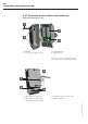

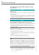
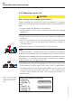
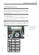
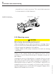
Table Of Contents
- Chapter 1: Introduction
- 1.1 First steps
- 1.2 Service addresses
- 1.3 About this manual
- Chapter 2: Safety
- 2.1 Safety symbols
- 2.2 Information for the system operator
- 2.3 Information for operating personnel
- 2.4 Intended use
- 2.5 Residual risks and safety measures
- Declaration of conformity
- Certifications
- Chapter 3: Technical data
- Chapter 4: System description
- 4.1 VIBCONNECT RF bridge
- 4.2 VIBCONNECT RF sensor unit
- 4.3 VIBCONNECT RF sensor
- Chapter 5: Installation & commissioning
- 5.1 Quick guide
- 5.2 Configuration in OMNITREND
- 5.3 Installation & commissioning of bridge
- 5.4 Installation & commissioning of sensor unit
- 5.5 Installation of sensors
- 5.6 Configuration in OMNITREND (continued)
- 5.7 Installing additional sensor unit
- Chapter 6: Maintenance
- 6.1 Cleaning
- 6.2 System time correction
- 6.3 Installation report
- 6.4 Battery-powered sensor unit
- 6.5 Update
- 6.6 Warranty
- 6.7 Spare parts and accessories
- Chapter 7: Troubleshooting
- Chapter 8: After use

46
VIBCONNECT RF 05.2012
1B-8F-DC-4C-00-36
1B-8F-DC-4C-00-38
Channel 1
Channel 3
Channel 2
Channel 4
• In the measurement location report, document the channel as-
signment of the measurement locations.
Sensor unit with external 24 V power supply:
• Connect the power supply cable to the second, 4-pin terminal
strip (see also '5.4.1 Overview of connections and interfaces',
page 40).
• Tighten the cable glands at the sensor unit and close the housing.
5.4.5 Commissioning sensor unit
• Switch on the power supply of the sensor unit by inserting the
batteries or switching on 24 V power supply respectively.
• Secure the batteries where appropriate with the included clamp
bars
Note
Maintaining battery charge
Until the sensor unit has received a valid measuring configuration
from the bridge, it continuously sends out requests, using battery
power.
» If you wish to program the measuring configuration at a later
stage, switch off battery-powered sensor units by removing
one battery.
Installation and commissioning
Clamp bar for battery