
Installation and Operation Guide
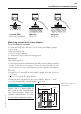
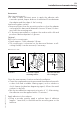
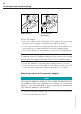

Table Of Contents
- Chapter 1: Introduction
- 1.1 First steps
- 1.2 Service addresses
- 1.3 About this manual
- Chapter 2: Safety
- 2.1 Safety symbols
- 2.2 Information for the system operator
- 2.3 Information for operating personnel
- 2.4 Intended use
- 2.5 Residual risks and safety measures
- Declaration of conformity
- Certifications
- Chapter 3: Technical data
- Chapter 4: System description
- 4.1 VIBCONNECT RF bridge
- 4.2 VIBCONNECT RF sensor unit
- 4.3 VIBCONNECT RF sensor
- Chapter 5: Installation & commissioning
- 5.1 Quick guide
- 5.2 Configuration in OMNITREND
- 5.3 Installation & commissioning of bridge
- 5.4 Installation & commissioning of sensor unit
- 5.5 Installation of sensors
- 5.6 Configuration in OMNITREND (continued)
- 5.7 Installing additional sensor unit
- Chapter 6: Maintenance
- 6.1 Cleaning
- 6.2 System time correction
- 6.3 Installation report
- 6.4 Battery-powered sensor unit
- 6.5 Update
- 6.6 Warranty
- 6.7 Spare parts and accessories
- Chapter 7: Troubleshooting
- Chapter 8: After use

50
VIBCONNECT RF 05.2012
• Clean the drill hole and the area around it with compressed
air; roughen the surface around the drill hole with sandpaper
(grade 220).
• Clean the contact faces at the adapter and the machine with
solvent.
• Allow the contact faces to dry, apply a thin layer of screw locking
agent (LOCTITE 243) to improve signal propagation.
• Screw the threaded bolt into the sensor and tighten it with
a size 4 Allen key.
• Screw the sensor into the mounting hole and tighten it with
a size 19 socket wrench. Tightening torque: 10 – 20 Nm!
• Check the sensor for proper fixture (sensor must not rock).
Notes
Do not apply an excessive torque as this could damage the machine
part or the thread at the sensor. If the tightening torque is too low,
there might be insufficient contact between the sensor and the
measurement location. Incorrect tightening torques result in incor-
rect measurements!
When installing sensors to machine parts that are not earthed
(e.g. belt-driven fans), connect the sensors to an earthing conduc-
tor to prevent static charging.
Installation and commissioning
Mounting sensor with adhesive adapter
tools and auxiliary equiPment
Hand drill and drill bit (3.5 mm) with depth gauge
Compressed air to clean mounting point
Two-component adhesive (e.g. WEICON HB 300)
File and size 19 torque wrench
Note
Before mounting the adapter, shut down the machine. Do not
restart the machine for a period of 24 hours to prevent mechanical
vibration while the adhesive is curing.
If the machine is restarted before the adhesive has properly
cured, the adapter might become loose. This can cause damage
to the sensor and / or to the machine. Incorrectly installed adhesive
adapters can result in poor signal propagation to the sensor and
measuring errors.