
Installation Manual Owner's manual

PS Engineering
PCD7100 Series Intercom System with Integral Music System
Installation and Operator’s Manual
200-971-0006 Page 2-5 Rev. 8, Jan. 2015
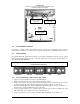
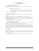
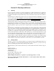
Figure 2-1- PCD7100 Adjustments
2.6 Post Installation Checkout
After wiring is complete, verify power is ONLY on pin 21 of the connector, and airframe ground on bottom
connector pin 22. Failure to do so will cause serious internal damage and void PS Engineering's warranty.
2.7 Unit Installation
To install the PCD7100, gently slide the unit into the mounting rack until the hold-down screw is engaged.
While applying gentle pressure to the face of the unit, tighten the 3/32" hex-head in the unit until it is se-
cure. DO NOT OVER TIGHTEN.
Warning: Do not over-tighten the lock down screw while installing the unit in tray.
Internal damage will result.
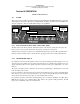
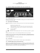
Play/Pause Skip-FF Repeat-RW Stop Eject
2.7.1 Intercom Checkout (11950, 11951, 11956, 11957)
1. Apply power to the aircraft and avionics. Leave PCD7100 off.
2. Plug headsets into the pilot, copilot, and occupied passenger positions.
3. Verify correct fail-safe operation by listening and transmitting on the aircraft radios in the pilot’s head-
set with the unit off. The audio will only be presented to the pilot’s right ear, in stereo mode.
4. Switch on the PCD7100. Verify that the STOP LED (Light Emitting Diode) shows green if there is a
CD in the unit, or the Eject LED if there is not a CD inside.
5. Verify proper transmit and receive operation from the pilot and copilot positions, noting that the copilot
PTT switch allows proper transmission on the selected transceiver.
6. Verify proper Intercom system operation in the ALL, ISO and CREW modes (see Table 3-1).
Passenger Intercom
volume (L)
Passenger Intercom
volume (R)
Front of Unit