9800 Martel Road Lenoir City, TN 37772 PM2CREW Intercom Expansion Unit Unit Part Number 11918, 11918R, 11918P6, 11918R6 11918P8, 11918R8 Passenger Intercom System Installation and Operation Manual Document P/N 200-005-0004 Revision 4 Sept. 2000 PS Engineering, Inc. 2000 © Copyright Notice Any reproduction or retransmittal of this publication, or any portion thereof, without the expressed written permission of PS Engineering, Inc. is strictly prohibited.
PS Engineering PM2Crew Expansion module (11918) Table of Contents SECTION I GENERAL INFORMATION 1.1 INTRODUCTION 1.2 SCOPE 1.3 DESCRIPTION 1.4 APPROVAL BASIS 1.5 SPECIFICATIONS 1.6 EQUIPMENT REQUIRED BUT NOT SUPPLIED 1-2 1-2 1-2 1-2 1-2 1-2 1-2 SECTION 2 INSTALLATION 2.1 GENERAL INFORMATION 2.2 UNPACKING AND PRELIMINARY INSPECTION 2.3 EQUIPMENT INSTALLATION PROCEDURES 2.4 CABLE HARNESS WIRING 2.4.1 ELECTRICAL NOISE ISSUES 2.4.2 POWER REQUIREMENTS 2.4.3 INTERCONNECTION WITH MAIN UNIT 2.4.
PS Engineering PM2Crew Expansion module (11918) Section I General Information 1.1 Introduction The PM2Crew is a panel mounted, multi-place intercom expansion unit used to add extra stations to an intercom system. Please read this manual completely before installation to minimize the risk of damage to the unit and to become familiar with all the features. 1.
PS Engineering PM2Crew Expansion module (11918) Section 2 Installation 2.1 General Information The PM2CREW comes with all necessary hardware for a typical installation. The unit is installed either in the panel (11918) or mounted blindly (11918R). If panel mounted, it can be installed near the audio panel, or a panel near the passengers. If blind mounted, it can be mounted nearly anywhere. If blind mounted, the squelch control should be mounted in a location convenient to the passengers.
PS Engineering PM2Crew Expansion module (11918) For panel mounted installation 1. Using the template, drill four holes in the instrument panel in a location convenient to the pilot or passengers position(s). 2. Insert the PM2CREW from behind the instrument panel, aligning the holes for the knobs. 3. Place the aluminum faceplate over the knob shafts and secure, using the two # 4-40 round head screws provided. 4. Apply the PM2Crew label to the panel, using care to align the holes over the knob shafts. 5.
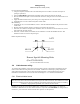
PS Engineering PM2Crew Expansion module (11918) Ground loop noise occurs when there are two different return paths for the same signal, such as airframe and ground return wire. Large cyclic loads such as strobes, inverters, etc., can inject audible signals onto the airframe return path. Follow the wiring diagram very carefully to help insure a minimum of ground loop potential. Radiated signals can be a factor when low level mic signals are bundled with current carrying power wires.
PS Engineering PM2Crew Expansion module (11918) Section III OPERATION Switching on the intercom or PMA4000 automatically activates the PM2CREW unit. . 3.1 Adjusting The Volume The volume control and squelch controls only affect the headsets connected to the PM2CREW directly, and not the main unit. 3.2 Adjusting The Squelch Control The PM2CREW provides individual VOX circuits for passenger 1, passenger 2, and another for passengers’ three and four.
PS Engineering PM2Crew Expansion module (11918) Appendix B Instructions for FAA Form 337 One method of airworthiness approval is through an FAA Form 337, Major Repair and Alteration (Airframe, Powerplant, Propeller, or Appliance) In the case of the PM2CREW part number 11918, you may use the following text as a guide. Installed 4-place intercom expansion unit, PS Engineering PM2CREW, part number 11918 in ( location ) at station . Installed per AC43.13-2, Chapter 2, paragraph 23 (Instrument Panel Mounting).
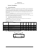
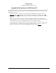
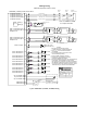
PS Engineering PM2Crew Expansion module (11918) Appendix D Wiring Information PM2CREW (11918) Female Sub-D DB-25 1 Expansion Power In Expansion Audio In (R) 2 15 Expansion Audio In (L) Expansion Audio Output 3 14 Expansion Ground NOTE Music (L) Music (R) 6 25 13 PM2000 Series PM1000 Series 17 5 18 4 1 15 16 17 4 3 2 5 3 Expansion Power Audio (right) from Main Unit Audio (left) from Main Unit Audio to Main Unit Expansion Ground See unit Installation manual for complete information Entertainment I
PS Engineering PM2Crew Expansion module (11918) PM2CREW (11918P6) Female Sub-D DB-25 1 Expansion Power In Expansion Audio In (R) 2 15 Expansion Audio In (L) Expansion Audio Output 3 14 Expansion Ground NOTE Music (L) Music (R) 6 25 13 PM2000 Series PM1000 Series PMA4000 Bottom Connector 17 5 18 4 1 15 16 17 4 3 2 5 3 Expansion Power Audio (right) from Main Unit Audio (left) from Main Unit Audio to Main Unit Expansion Ground See unit Installation manual for complete information Entertainment Inpu
PM2Crew Expansion module (11918) PS Engineering PM2CREW (11918R8) Female Sub-D DB-25 1 2 15 3 14 Expansion Power In Expansion Audio In (R) Expansion Audio In (L) Expansion Audio Output Expansion Ground 9 21 8 20 Music (L) 25 Music (R) 13 Pass 1 & 3 Phones (L) Hi Pass 1 & 3 Phones (R) Hi Headphone Lo Pass 2 & 4 Phones (L) Hi Pass 2 & 4 Phones (R) Hi Headphone Lo Mono Aux input 22 4 16 Pass 5 Mic Audio Hi Pass 5 Mic Audio Lo 17 Pass 1 Mic Audio Hi Pass 1 Mic Audio Lo Pass 2 Mic Audio Hi Pass 2 Mi