9800 Martel Road Lenoir City, TN 37772 www.ps-engineering.com PMA5000EX Document P/N 200-550-0100 Rev. 1, January 2011 Audio Selector Panel with 4-Place IntelliVox® Stereo Intercom System Installation and Operation Manual Patented under one or more of the following; No.
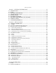
Table of Contents Section I – GENERAL INFORMATION .................................................................1-1 1.1 1.2 1.3 1.4 1.5 1.6 1.7 1.8 1.9 INTRODUCTION...................................................................................................................... 1-1 SCOPE ....................................................................................................................................... 1-1 EQUIPMENT DESCRIPTION ....................................................
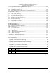
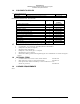
PS Engineering PMA5000EX Audio Selector Panel and Intercom System Installation and Operator’s Manual 3.3 COMMUNICATIONS TRANSMIT (XMT) SELECTION (2) ................................................................ 3-1 3.3.1 3.3.2 3.3.3 3.4 3.5 SPLIT MODE ................................................................................................................ 3-2 COM RADIO MONITOR (3) ...........................................................................................
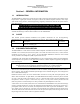
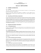
PS Engineering PMA5000EX Audio Selector Panel and Intercom System Installation and Operator’s Manual Section I – GENERAL INFORMATION 1.1 INTRODUCTION The PMA5000EX is designed to provide the basic audio control and intercom features most desire for the Experimental / Light Sport Aircraft owner/pilot. Features like cellular telephone interface, music input with custom muting schemes, and PS Engineering’s legendary IntelliVox® make this the perfect unit for many light aircraft.
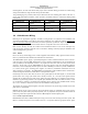
PS Engineering PMA5000EX Audio Selector Panel and Intercom System Installation and Operator’s Manual 1.4 APPROVAL BASIS **None** The PMA5000EX is NOT INTENDED OR APPROVED for installation or use in a certified aircraft. Operation is subject to the following conditions: This device may not cause harmful interference. This device must accept any interference received, including interference that may cause undesired operation. 1.5 SPECIFICATIONS WEIGHT 1.34 lb. (0.61 kg) PMA5000EX Unit 0.51 lb. (0.
PS Engineering PMA5000EX Audio Selector Panel and Intercom System Installation and Operator’s Manual 1.6 EQUIPMENT SUPPLIED 1 ea. of the following units: Model PMA5000EX Description PMA5000EX Audio Panel with Stereo intercom. Part Number 050-550-0200 PMA5000EX Installation Kit: 250-890-0000 Description 1.
PS Engineering PMA5000EX Audio Selector Panel and Intercom System Installation and Operator’s Manual Section II - INSTALLATION 2.1 2.1.1 GENERAL INFORMATION SCOPE This section provides detailed installation and interconnectio n instructions for the PS Engineering PMA5000EX Audio Selector Panel/Intercom. Please read this manual carefully before beginning any installation to prevent damage and post installation problems.
PS Engineering PMA5000EX Audio Selector Panel and Intercom System Installation and Operator’s Manual mounting block, 431-891-0100. Ensure that proper strain relief and chafing precautions are made during wiring and installation, using the cable clamp (625-001-0002). Two grounding lugs are provided, which may be attached to the rear mounting plate with 2 ea #4 -40 x ¼” screws with captivated lock washers. These provide a convenient location to connect the shield ground terminations.
PS Engineering PMA5000EX Audio Selector Panel and Intercom System Installation and Operator’s Manual and ground connections are made directly to the dedicated music signal and grou nd inputs on the PMA5000EX. The power for IFE and audio panel should be a common bus. If a music jack instead of a music source is installed for Music 1 or 2, we recommend grounding the jack to airframe ground.
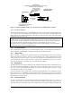
PS Engineering PMA5000EX Audio Selector Panel and Intercom System Installation and Operator’s Manual Cellular Plug (typical) Cellular Phone Tip= Microphone out Ring= Speaker audio Interconnect Base=Ground PMA5000EX J1 3 5 4 Com 3 Audio COM 3 Mic Input Audio Lo 3/32" Cellular Jack This is a typical interconnect PS Engineering does not guarantee compatability in all cases. Figure 2-1 Cellular telephone interface for rear connector, if an additional jack is desired 2.4.5.
PS Engineering PMA5000EX Audio Selector Panel and Intercom System Installation and Operator’s Manual waypoint audio, autopilot disconnect tones, or any other critical audio signal. Unswitched #1 is always presented to the to the crew headphones, and is available to the pilot in fail -safe (off) mode. Unswitched 3 and 4 inputs are always presented to the crew headphones.
PS Engineering PMA5000EX Audio Selector Panel and Intercom System Installation and Operator’s Manual 2.5.2 Entertainment muting The PMA5000EX-system incorporates a "Soft Mute™" system. This will mute the entertainment devices during ICS or radio conversation. See Section 3.7 for more information. Any signal appearing in the hard wired unswitched audio inputs will always mute the entertainment sources, even though the passengers may not hear the audio tone itself.
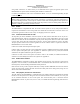
PS Engineering PMA5000EX Audio Selector Panel and Intercom System Installation and Operator’s Manual Shorter Screw Front of unit NOTE: If top cover is removed for ANY reason, you MUST replace the cover screws with the proper length, otherwise damage will result. Figure 2-2- PMA5000EX Adjustments, top cover Figure 2-3 – Unswitched 3 Audio Level (bottom cover removed) 2.6.1 Microphone Gain Selection In very high noise environments (such as open cockpit, etc.
PS Engineering PMA5000EX Audio Selector Panel and Intercom System Installation and Operator’s Manual 2.
PS Engineering PMA5000EX Audio Selector Panel and Intercom System Installation and Operator’s Manual 2.9 Post Installation Checkout After wiring is complete, verify power is ONLY on pins 8 and 9 of the J2 and airframe ground on J2 connector pins 10 and 11. Failure to do so will cause serious internal damage and void PS Engineering's warranty. 2.10 Unit Installation To install the PMA5000EX, gently slide the unit into the mounting rack until the hold -down screw is engaged.
PS Engineering PMA5000EX Audio Selector Panel and Intercom System Installation and Operator’s Manual 2.11.2 TEL Checkout Press the TEL button. Verify that the pilot headset is connected to the cellular telephone system (if i nstalled). Verify that by using the pilot side PTT, the pilot can transmit on the other selected radio (Com 1 or Com 2). The telephone function will allow any person heard by the pilot on the intercom, also heard on the telephone. 2.
PS Engineering PMA5000EX Audio Selector Panel and Intercom System Installation and Operator’s Manual Section III OPERATION 3.1 SCOPE This section provides detailed operating instructions for the PS Engineering PMA5000EX, Audio Selector Panel/Intercom Systems. Please read it carefully before using the equipment so that you can take full a dvantage of its capabilities. This section is divided into sections covering the basic operating areas of the PMA5000EX systems.
PS Engineering PMA5000EX Audio Selector Panel and Intercom System Installation and Operator’s Manual the pilot having to switch Com 1 audio back on, after changing transmitters. When switching from COM 1 to COM 2 while Com 2 was not previously selected, COM 1 audio will be switched off. In essence, switching the mic selector will not override prior selection of COM receiver audio. In normal (not split) modes, the PMA5000EX gives priority to the pilot’s radio Push-To-Talk (PTT).
PS Engineering PMA5000EX Audio Selector Panel and Intercom System Installation and Operator’s Manual through when the AUX 2 button is selected. When one of these buttons is pressed, the mode is active, and the LED will illuminate. Press the switch again and it will be "off" and remove that receiver from the a udio output. In SPLIT mode, only the pilot will hear selected navigation audio. 3.
PS Engineering PMA5000EX Audio Selector Panel and Intercom System Installation and Operator’s Manual Table 3-1 Mic Muff ™ Part Numbers Manufacturer Bose David Clark Lightspeed Model Dynamic Electret M87 Dynamic H10-30 H10-20, H10-40 H10-13.4 All Peltor 7003 7004 90010 90015 Pilot 11-20 & 11-90 90015 Sennheiser Telex 3.6.
PS Engineering PMA5000EX Audio Selector Panel and Intercom System Installation and Operator’s Manual 3.7 Music Muting (6) There are two SoftMute™ muting circuits. The front panel "Mute" button has four modes, and controls the Mute function for music 1. Music 2 muting is controlled by an external switch, and has two modes. The SoftMute™ circuit will cut the music out whenever there is conversation on the radio, the intercom, or both, depending on the “Mute” mode selected.
PS Engineering PMA5000EX Audio Selector Panel and Intercom System Installation and Operator’s Manual The volume changes about three steps per second, so it takes about 10 seconds to ramp the volume across the full range. It is possible to turn the volume completely off, so try pressing the volume up button if you don’t hear music as expected. 3.9 Telephone Mode (9) The TEL mode serves as a full duplex interface for compatible telephone systems such as portable cellular phones with earpiece jacks.
PS Engineering PMA5000EX Audio Selector Panel and Intercom System Installation and Operator’s Manual 3.10.2.1 Smart Jack Function When the PMA5000EX has a signal on music #1 input coming in from the rear connector, the front panel jack automatically becomes a Priority Advisory input, and is heard in the crew headphones. NOTE The front jack is no substitute for the installation of alerts such as the GPS waypoint or autopilot tones. These still must be hard wired into the back by your installer. 3.10.
PS Engineering PMA5000EX Audio Selector Panel and Intercom System Installation and Operator’s Manual When the music is standard, Music 1 will always go to the pilot and copilot positions, and is never heard by the passengers. Music 2 is always heard by the passengers, and never heard by the pilot and copilot. This mode is useful if your passengers have a different interest in entertainment or are watching a DVD, but do not want to be excluded from the intercom conversations. 3.10.
PS Engineering PMA5000EX Audio Selector Panel and Intercom System Installation and Operator’s Manual Section IV – Warranty and Service 4.1 Warranty In order for the factory warranty to be valid, the installations must be accomplished by an authorized PS Engineering dealer. If the unit is being installed by a non -certified individual in an experimental aircraft, a factory-made intercom harness must be used for the warranty to be valid. PS Engineering, Inc.
PS Engineering PMA5000EX Audio Selector Panel and Intercom System Installation and Operator’s Manual Appendix A – External PTT Hook Up Part of the installation includes the installation of PTT (Push To Talk) switches that allow the use of your aircraft radio for communications tran smissions. There are three possible configurations; you must select the case that best fits your installation. NOTE: Only the person who presses their PTT switch will be heard over the radio.
PS Engineering PMA5000EX Audio Selector Panel and Intercom System Installation and Operator’s Manual Appendix B – PMA5000EX Installation Drawings 475-013-0001 Lock nut (4 ea) 44-pin connector (2 ea) 475-440-0004 (4 ea) 475-440-0007 (4 ea) Rack back plate 430-890-0050 Rack 430-890-0040 Ground Lug 475-440-0001 (x2) J2 J1 1 15 30 16 31 44 Back plate assy 1 15 30 475-440-0001 (x2) Screw w/washer 16 31 44 475-009-0001 ground lug (x2) Viewed from Back Ground Lug Ground lug detail Rear plate detail
PS Engineering PMA5000EX Audio Selector Panel and Intercom System Installation and Operator’s Manual Appendix C – J1 Connector Interconnect 200-550-0100 Appendix C Rev. 1 Jan.
PS Engineering PMA5000EX Audio Selector Panel and Intercom System Installation and Operator’s Manual Appendix D – J2 Connector Interconnect 200-550-0100 Appendix D Rev. 1 Jan.