
Installation Manual Owner manual

PS Engineering
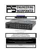
PMA5000EX Audio Selector Panel and Intercom System
Installation and Operator’s Manual
200-550-0100 Page 1-3 Rev. 1 Jan. 2011
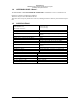
1.6 EQUIPMENT SUPPLIED
1 ea. of the following units:
Model
Description
Part Number
PMA5000EX
PMA5000EX Audio Panel with Stereo intercom.
050-550-0200
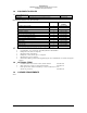
PMA5000EX Installation Kit: 250-890-0000
Description
Quantity
Part
Number
Installation rack assembly
1
430-890-0040
Rack back plate
1
430-890-0050
44-pin connector kit
2
120-891-2045
Backshell, connector
2
625-025-2465
Backshell Retainer
2
431-881-0100
4 40 X 7/16 screw w/nylon patch
4
475-440-0007
4 40 X 3/8 screw w/nylon patch
4
475-440-1038
4-40 x ¼” screw with lock washer
2
475-440-0001
Solder Lug
2
475-009-0001
Cable Clamp
1
625-001-0002
#6-32 x ½” Flat head Philips screw
6
475-632-0012
#6-32 Clip Nut
6
475-630-0002
Parts ID Sheet
1
002-890-0404
1.7 EQUIPMENT REQUIRED BUT NOT SUPPLIED
a. Circuit Breaker: 1 ea; 5 amp PULL TYPE REQUIRED for PMA5000EX
b. Headphone Jacks (Stereo, as Required)
c. Microphone Jacks (as Required)
d. Headphones, 150 (Stereo), up to 6 as required
e. Microphones, up to 4 as required
f. Interconnect Wiring (contact PS Engineering for more information on custom wiring har-
nesses).
1.8 OPTIONAL ITEMS
a. Cell Phone Patch Cord, 2.5mm to 2.5mm, PS Part Number 425-006-7026
b. Music Patch Cord, 3.5mm to 5.5mm, PS Part Number 425-006-2535
c. Phone patch cord for iPhone or Blackberry 3.5 mm 4-conductor to 2.5 mm
(Phone only, no music) 425-006-0354
1.9 LICENSE REQUIREMENTS
None