
Installation manual

PS Engineering
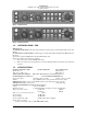
PMA6000 Series Audio Selector Panel and Intercom System
Installation Manual
200-066-0100 Page 2-1 Rev. 1, March 2005
Section II -Installation
2.1 GENERAL INFORMATION
2.1.1 SCOPE
This section provides detailed installation and interconnect instructions for the PS Engineering PMA6000-
Series Audio Selector Panel/Intercom System and PMA6000M-Series Audio Selector Panel/Intercom Sys-
tem with internal Marker Beacon.
With the exception of the internal marker beacon receiver, the PMA6000, and PMA6000C are identical to
the PMA6000M, PMA6000M-C. All units will be identified hereafter as the PMA6000, where the infor-
mation applies to all.
Please read this manual carefully before beginning any installation to prevent damage and post installation
problems. Installation of this equipment requires special tools and knowledge. The equipment must be
installed by an appropriately rated Certified Aircraft Repair Station, in accordance with applicable regula-
tions.
NOTE: The PMA6000-Series requires specialized knowledge equipment and tools for an effective instal-
lation. An appropriately rated Certified Aircraft Repair Station must install this equipment in accordance
with applicable regulations. PS Engineering, Incorporated warranty is not valid unless the equipment is
installed by an authorized PS Engineering, Incorporated dealer. Failure to follow any of the installation
instructions, or installation by a non-certified individual or agency will void the warranty, and may result in
an unairworthy installation.
2.2 Unpacking and Preliminary Inspection
Use care when unpacking the equipment. Inspect the units and parts supplied for visible signs of shipping
damage. Examine the unit for loose or broken buttons, bent knobs, etc. Verify the correct quantity of com-
ponents supplied with the list in Section 1.6 (B). If any claim is to be made, save the shipping material and
contact the freight carrier. Do NOT return units damaged in shipping to PS Engineering. If the unit or ac-
cessories shows any sign of external shipping damage, contact PS Engineering to arrange for a replace-
ment. Under no circumstances attempt to install a damaged unit in an aircraft. Equipment returned to PS
Engineering for any other reason should be shipped in the original PS Engineering packaging, or other
UPS approved packaging.
2.3 Equipment Installation Procedures
2.3.1 Cooling Requirements
Forced-air cooling of the PMA6000 is not required. However the unit should be kept away from heat pro-
ducing sources (i.e. defrost or heater ducts, dropping resistors, heat producing avionics) without adequate
cooling air provided.
NOTICE: To reduce the amount of heat dissipated in the audio selector panel, when used in a 28
Volt aircraft, it is required that the 15 Ω, 15-Watt dropping resistor (p/n 701-015-1501) be in-
stalled in series with the power input.
If the PMA6000/M-S is installed in a 27.5 VDC aircraft system, a 15 Ω, 15 Watt dropping resistor (p/n
701-015-1501) should be installed. Failure to do so will generate unnecessary heat inside the unit and may
void PS Engineering's warranty.