
Specifications


PS Engineering
PMA7000M-S Series Audio Selector Panel and Intercom System
Civil Air Patrol Version Installation and Operator’s Manual
200-072-0004 Page 2-8 Rev. 4, Sept. 2000
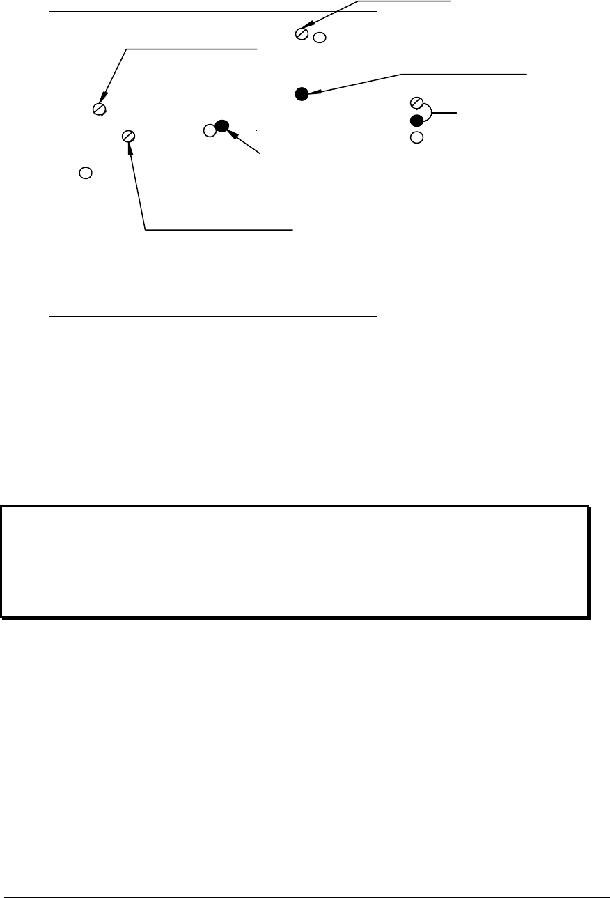
Marker Gain
CW- Reduce
Passenger Volume
CCW Increases
Marker Audio
CW Decrease Volume
MKR Low Sense
CW Decrease Sens.
Front of Unit
PMA 7000 adjustment holes
Not used
Speaker Volume
CW-Increase
Figure 2-1- PMA7000M-S Adjustments
2.8 Communications Antenna Installation Notes
For best results while in Split Mode, it is suggested that the one VHF communications antenna
is located on top of the aircraft while the other communications antenna is installed on the
bottom. Any antenna relocation must be accomplished in accordance with AC 43.13-2A,
aircraft manufacturers’ recommendations and FAA-approved technical data.
Warning:
It is probable that radio interference will occur in the split mode when the frequencies of the
two aircraft radios are adjacent, and/or the antennas are physically close together. PS
Engineering makes no expressed or implied warranties regarding the suitability of the
PMA7000M-S in Split Modes.
2.9 Post Installation Checkout
After wiring is complete, verify power is ONLY on pin 20 of the J1 (bottom connector) (dim
power may also be at Pin D and F), and airframe ground on bottom connector pin Z. Failure to
do so will cause serious internal damage and void PS Engineering's warranty.
2.10 Unit Installation
To install the PMA7000M-S, gently slide the unit into the mounting rack until the hold-down
screw is engaged. While applying gentle pressure to the face of the unit, tighten the 3/32" hex-
head in the canter of the unit until it is secure. DO NOT OVER TIGHTEN.