
Specifications


PS Engineering
PMA7000M-S Series Audio Selector Panel and Intercom System
Installation and Operator’s Manual for Civil Air Patrol
200-072-0004 Appendix C Rev. 4, Sept. 2000
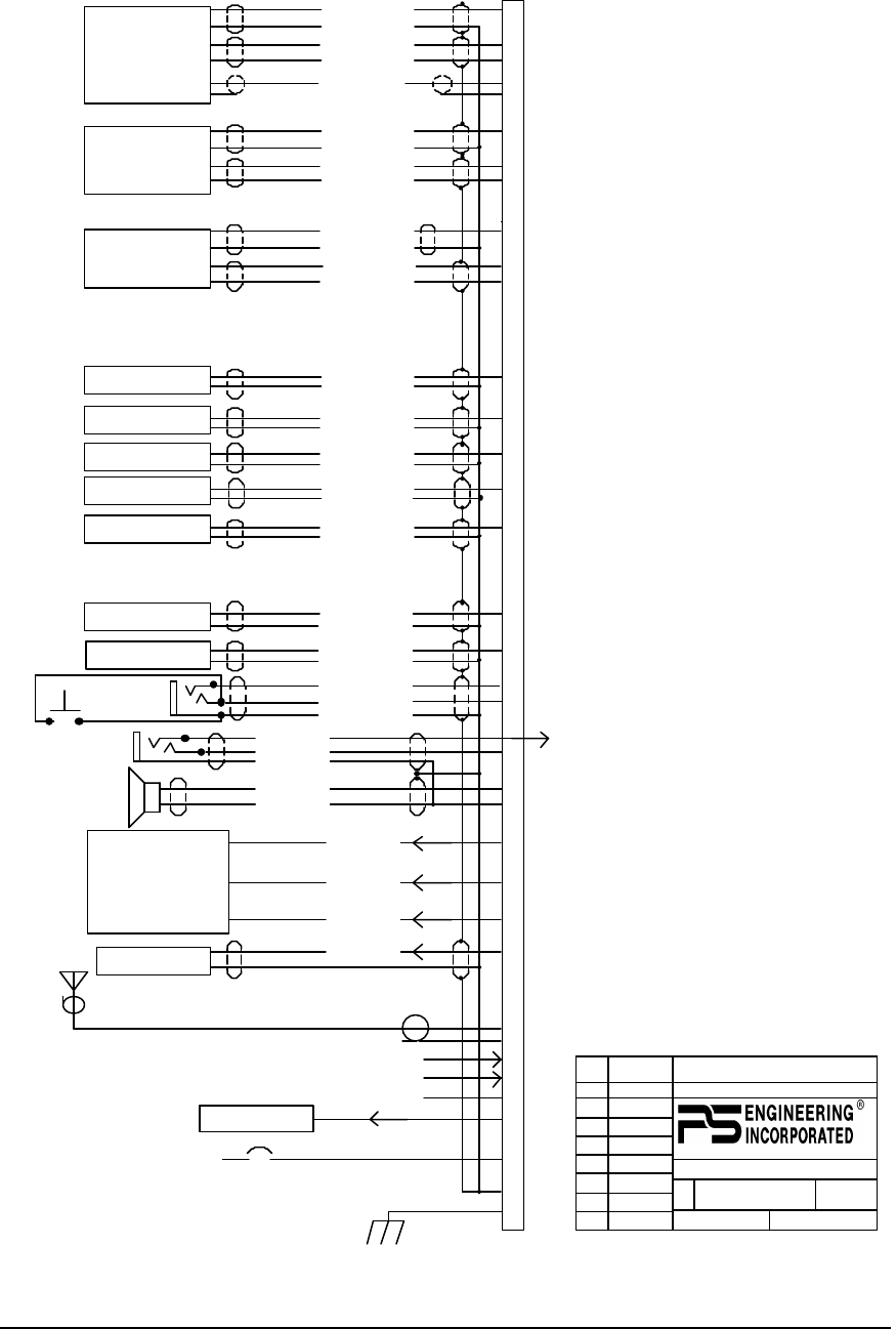
Appendix C Bottom Connector Interconnect
Com 1 Audio Hi
Com 1 Mic Key
Com 1 Lo
Communications
Transceiver #1
Communications
Transceiver #2
Nav 1 Audio Hi
NAV 1 Audio Lo
VHF Nav 1
Nav 2 Audio Hi
Nav 2 Audio Lo
VHF Nav 2
DME Audio Hi
DME Audio Lo
DME Receiver
Com 1 SPR Load
Unswitched Input #1 Hi
Unswitched Audio Lo
Unswitched Audio #1
Unswitched Input #2 Hi
Unswitched Audio Lo
Unswitched Audio #2
Pilot Mic Audio Hi
Pilot Mic PTT
Pilot Mic Lo
Ext. Marker Lamp (Blue)
C
5
4
2
Ext. Marker Lamp (White)
Ext. Marker Lamp (Amber)
MM Sense Output
MKR Ant.
B
A
White Lamp Output
Blue Lamp Output
Amber Lamp
MM Sense
RG-58A/U Coax
PA Mute Trigger
F
D
E
18
20
1
Z
W
22
28 Volt Lights Hi
14 V Lights Hi
Lights Lo
Ground
Airframe Ground
3A (28VDC)
11-33 VDC
9
P
R
Com 1 Mic Audio Hi
Com 2 Audio Hi
Com 2 Key
Com 2 Audio Lo
10
H
V
Com 2 Mic Audio Hi
12
13
6
19
L
Com 1 Spr Load
Com 1 Spr Load
16
M
T
17
Speaker Hi
Speaker Lo
3
Pilot Phones (L)
Pilot Phones (R)
Pilot Phones Lo
8
Y
To Pin 1
Top Conn.
Communications
Transceiver #3
J
K
15
Com 3 Audio Hi
Com 3 Mic Audio Hi
Com 3 Lo
Com 3 Mic Key
Mkr Audio In Hi
Mkr Audio In Lo
Ext. Mkr Audio
21
ADF Audio Hi
ADF Audio Lo
ADF Receiver
S
11
Notes:
1. Pins 7, U, 11, and X not used.
2. All shields should be grounded
at audio panel only.
Other end remains floating.
3. Speaker and Pilot Headphone
ground returns MUST be kept
separate and connected to pin 22.
4. All Power and Ground wires must
be #18 gage wire
5. Pilot mic and headphone jacks must
be isolated from ground.
6. Pin 20 connected through a 3 A
breaker.
7. PA Mute is a TTL level logic output
that is pulled low when PTT active.
8. Speaker loads may be reqired on some
transceivers. Consult manufacturer's
information.
9. Reserved
10. Reserved
11. All shielded wires must be MIL 22759
or 27500.
12. For stereo installation, connect
pilot headphone (L) to top connector,
Pin 1, using 3-conductor wire.
13. Key pin between pin 7 and 8.
A
REV
DATE:
SHEET OF
TITLE:
DOCUMENT NUMBER:SIZE
PMA7000 Bottom Connector Wiring (CAP)
120-070-0211 1
11/11/98
1
1
9800 MARTEL ROAD, LENOIR CITY TN 37922
Ext. Marker Annunciator
DWN
CKD
APR
DATE
DATE
DATE
GLP
11/11/98
Pilot PTT
See Note 4, 9
See Note 7
See Note 4, 9
See Note 3
See Note 8
11/11/98
11/11/98
GLP
See Note 12
Bottom Connector, J1
REV GLP Remove AUX input
REV GLP Clean up notes
All wires #24 awg minimum unless noted