9800 Martel Road Lenoir City, TN 37772 www.ps-engineering.com PMA8000 Document P/N 200-890-0000 Revision 10, September 2005 Audio Selector Panel with Marker Beacon Receiver High-fidelity Stereo Intercom System Installation and Operation Manual FAA-Approved TSO C50c, C35d Patented under one or more of the following; No. 5,903,277; 6,160,496 and 6,493,450 In certified aircraft, warranty is not valid unless this product is installed by an Authorized PS Engineering dealer. PS Engineering, Inc.
Table of Contents Section I GENERAL INFORMATION..................................................................... 1-1 1.1 1.2 1.3 1.4 1.5 1.6 1.7 1.8 INTRODUCTION ......................................................................................................................... 1-1 SCOPE............................................................................................................................................ 1-1 EQUIPMENT DESCRIPTION...............................................
PS Engineering PMA8000 Series Audio Selector Panel and Intercom System Installation and Operator’s Manual 2.11.5 2.12 INTERNAL RECORDER CHECKOUT (OPTIONAL)......................................................... 2-11 FINAL INSPECTION ...................................................................................................................... 2-11 Section III OPERATION........................................................................................... 3-1 3.1 3.2 3.3 SCOPE...............
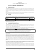
PS Engineering PMA8000 Series Audio Selector Panel and Intercom System Installation and Operator’s Manual Section I GENERAL INFORMATION 1.1 INTRODUCTION The PMA8000 represents another evolutionary step in cockpit audio control and intercommunications utility. Using our patented IntelliVox® design, this unit eliminates the requirements for intercom squelch adjustments. The unit is designed for outstanding ergonomics and visually defined mode annunciation and selection.
PS Engineering PMA8000 Series Audio Selector Panel and Intercom System Installation and Operator’s Manual controls the intercom level for the pilot and copilot, while the large knob controls the passenger intercom volume. Intercom squelch is automatic. A 3-light Marker Beacon receiver is integrated in the PMA8000. This provides the necessary Marker Beacon lights and audio indications necessary for an Instrument Landing System (ILS) approach.
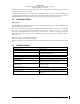
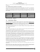
PS Engineering PMA8000 Series Audio Selector Panel and Intercom System Installation and Operator’s Manual Audio Selector Specifications Audio selector panel input impedance: 510 Ω Input Isolation: -60 dB (min.) Speaker Muting: -60 dB (min.) Speaker Output (into 4 Ω) with no clipping 3 Watts (min.) 14 VDC: 10 Watts (min.
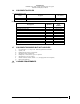
PS Engineering PMA8000 Series Audio Selector Panel and Intercom System Installation and Operator’s Manual 1.6 EQUIPMENT SUPPLIED 1 ea. of the following units: Model PMA8000 PMA8000 with option 1 Description Part Number PMA8000 Audio Panel with Marker Beacon and Stereo intercom.
PS Engineering PMA8000 Series Audio Selector Panel and Intercom System Installation and Operator’s Manual Section II - Installation 2.1 GENERAL INFORMATION 2.1.1 SCOPE This section provides detailed installation and interconnection instructions for the PS Engineering PMA8000-Series Audio Selector Panel/Intercom/ with internal Marker Beacon. Please read this manual carefully before beginning any installation to prevent damage and post-installation problems.
PS Engineering PMA8000 Series Audio Selector Panel and Intercom System Installation and Operator’s Manual FHP 6-32 x ½" screws (475-632-0012). The audio selector panel must be supported at front and rear of the mounting tray. 2.3.4 Audio Panel Tray and Connector Assembly The rack connectors mate with two 44-pin connectors in the PMA8000. The connectors are a sub miniature crimp-type, and require the use a hand crimp tool, from table below (or equiv.).
PS Engineering PMA8000 Series Audio Selector Panel and Intercom System Installation and Operator’s Manual NOTE: Adding a high-performance audio control system, particularly in conjunction with high-performance active noise canceling headsets, cannot improve on older avionics that were designed for cabin-speaker use. PS Engineering makes no claim that the audio panel will provide a noise-free audio quality under all installation conditions, particularly with older avionics. 2.4.
PS Engineering PMA8000 Series Audio Selector Panel and Intercom System Installation and Operator’s Manual Cellular Plug (typical) Tip= Microphone out Ring= Speaker audio Base=Ground Cellular Phone Interconnect Com 3 Audio COM 3 Mic Input Audio Lo 3/32" Cellular Jack This is a typical interconnect PS Engineering does not guarantee compatability in all cases.
PS Engineering PMA8000 Series Audio Selector Panel and Intercom System Installation and Operator’s Manual 2.4.11 Public Address Mode By pressing the Mute and SPR pushbuttons at the same time, the PMA8000 will be placed into public address (PA) mode. In this mode, both Com 1 and Com 2 receive indicators will blink, alerting the pilot that when he presses his PTT switch he will be talking over the cockpit speaker. Copilot will still continue on the selected COM radio.
PS Engineering PMA8000 Series Audio Selector Panel and Intercom System Installation and Operator’s Manual 24 23 25 Ent. #1 Input 27 26 28 Alternate Music Interconnect Note 7 Ent. #2 Input Music interconnect for Music 1 to drive both inputs 26 27 28 Ent. #2 Input 23 Ent.
PS Engineering PMA8000 Series Audio Selector Panel and Intercom System Installation and Operator’s Manual 2.4.14.1.2 Entertainment 2 Mute (J2 Pin 13 & 14) Connecting J2 pin 13 to pin 14 (or ground) through a SPST switch places the entertainment #2 music source into the Karaoke Mode. In this mode, incoming music and intercom conversation will not mute the music for the passengers’ intercom net.
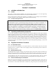
PS Engineering PMA8000 Series Audio Selector Panel and Intercom System Installation and Operator’s Manual Shorter Screw Front of unit MKR VOL NOTE: SPR VOL If top cover is removed for ANY reason, you MUST replace the cover screws with the proper length, otherwise damage will result. TEL VOL Figure 2-2- PMA8000 Adjustments • Speaker Volume- Turn adjustment clockwise to increase cabin speaker output. • Marker Beacon Volume, turn adjustment counterclockwise to increase marker beacon audio level.
PS Engineering PMA8000 Series Audio Selector Panel and Intercom System Installation and Operator’s Manual 2.
PS Engineering PMA8000 Series Audio Selector Panel and Intercom System Installation and Operator’s Manual 2.9 Post Installation Checkout After wiring is complete, verify power is ONLY on pins 8 and 9 of the J2 and airframe ground on connector pins 10 and 11. Failure to do so will cause serious internal damage and void PS Engineering's warranty. 2.10 Unit Installation To install the PMA8000, gently slide the unit into the mounting rack until the hold-down screw is engaged.
PS Engineering PMA8000 Series Audio Selector Panel and Intercom System Installation and Operator’s Manual 12. Verify proper operation of all receiver sources by selecting them using the appropriate button. The button illuminates to show which source is in use. 13. Push the SPR button. Verify that all selected audio is heard in the cockpit speaker. Verify that the audio mutes when the mic is keyed. 14. Verify that the appropriate LED in the lower button row blinks when either push to talk is keyed. 15.
PS Engineering PMA8000 Audio Selector Panel and Intercom System Installation and Operator’s Manual Section III OPERATION GENERAL INFORMATION 3.1 SCOPE This section provides detailed operating instructions for the PS Engineering PMA8000, Audio Selector Panel/Intercom Systems. Please read it carefully before using the equipment so that you can take full advantage of its capabilities. This section is divided into four sections covering the basic operating areas of the PMA8000 systems.
PS Engineering PMA8000 Audio Selector Panel and Intercom System Installation and Operator’s Manual Figure 2 PMA8000 Operating controls NOTE: Placing the PMA8000 in–TEL– The intercom mode pushbutton determines who is on the phone, and who is still on the intercom. In ISO, only the pilot is on the phone, while the copilot and passengers remain on intercom. The pilot will continue to hear all selected aircraft radios.
PS Engineering PMA8000 Audio Selector Panel and Intercom System Installation and Operator’s Manual 3.4.1.1 Public Address Function To access PA function, press the Mute (6) and SPR (5) buttons simultaneously. The COM1 and COM2 receive LEDs will blink to indicate the audio panel is in PA mode. The copilot can continue to use the selected com radio while the pilot will be heard over the speaker. To exit, press Mode and SPR again.
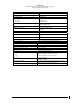
PS Engineering PMA8000 Audio Selector Panel and Intercom System Installation and Operator’s Manual Table 3-1 Mic Muff ™ Part Numbers Manufacturer Bose David Clark Lightspeed Model Dynamic Electret M87 Dynamic H10-30 H10-20, H10-40 H10-13.4 All Peltor 7003 7004 90010 90015 Pilot 11-20 & 11-90 90015 Sennheiser Telex 3.6.
PS Engineering PMA8000 Audio Selector Panel and Intercom System Installation and Operator’s Manual 3.6.3.1 Entertainment Input The audio selector panel has provisions for two separate entertainment input devices. Music 1 feeds the pilot and copilot positions. They operate independently in the PMA8000. The volume control does not affect the music level. Music 2 feeds the passengers. Passenger music also operates independently from the crew (music 1).
PS Engineering PMA8000 Audio Selector Panel and Intercom System Installation and Operator’s Manual PMA8000 can serve as a audio control and distribution center. When TEL is active, the button will blink about twice as fast as the normal transmit rate. In ALL intercom mode, all crew and passengers will be heard on the phone when they speak. All will hear selected audio. Com audio is automatically heard in the headsets. In CREW mode, the pilot and copilot are connected to the telephone.
PS Engineering PMA8000 Audio Selector Panel and Intercom System Installation and Operator’s Manual 200-890-0000 Page 3-7 Revsion 10, September 2005
PS Engineering PMA8000 Audio Selector Panel and Intercom System Installation and Operator’s Manual Section IV- Warranty and Service 4.1 Warranty In order for the factory warranty to be valid, the installations in a certified aircraft must be accomplished by an FAA-(or other ICAO agency) certified avionics shop and authorized PS Engineering dealer.
PS Engineering PMA8000 Audio Selector Panel and Intercom System Installation and Operator’s Manual Appendix A External PTT Hook Up Part of the installation includes the installation of PTT (Push To Talk) switches that allow the use of your aircraft radio for communications transmissions. There are three possible configurations ; you must select the case that best fits your installation. NOTE: Only the person who presses their PTT switch will be heard over the radio.
PS Engineering PMA8000 Audio Selector Panel and Intercom System Installation and Operator’s Manual Appendix B – PMA 8000 Installation Drawings 475-013-0001 Lock nut (4 ea) 44-pin connector (2 ea) 475-440-0004 (4 ea) 475-440-0007 (4 ea) Rack back plate 430-890-0050 Rack 430-890-0040 J2 J1 Viewed from Back 15 30 44 15 30 44 1 16 31 1 16 31 Solder Lug (mount as convenient) Rear plate detail (not to scale) 6.31in 1.28in 1.28 in 0.96in 0.36in 0.37in 3.87in 5.53in 6.
PS Engineering PMA8000 Audio Selector Panel and Intercom System Installation and Operator’s Manual Appendix C, J1 Interconnect PMA8000 Connector, J1 (Sub-D 44-pin, male on tray) Com 1 Audio Hi Notes: Com 1 Lo Communications Transceiver #1 Com 1 Mic Audio Hi Com 1 Mic Key Com 2 Audio Hi Communications Transceiver #2 Com 2 Lo Com 2 Mic Audio Hi Com 2 Mic Key See Note 4 Com 2 SPR Load 13 14 15 30 Com 2 Spr Load Com 2 Spr Load TEL Audio Hi TEL Audio Lo Telephone TEL Mic Audio Hi Nav 1 Audio Hi V
PS Engineering PMA8000 Audio Selector Panel and Intercom System Installation and Operator’s Manual Appendix D, J2 Connector Interconnect PMA8000 J2 CONNECTOR (Sub-D 44-pin male on tray) 44 43 Unswitched Audio #4 15 Unswitched Input #4 Hi Unswitched Audio Lo 35 36 Pass. Mic Hi Pass. Mic Lo 37 38 Pass. Mic Hi Pass. Mic Lo 39 40 Pass. Mic Hi Pass. Mic Lo 41 42 Pass. Mic Hi Pass. Mic Lo Copilot Mic Audio Copilot Mic Jack Copilot PTT Copilot Mic Lo 24 23 25 Ent. #1 Audio (R) Ent.
PS Engineering PMA8000 Audio Selector Panel and Intercom System Installation and Operator’s Manual Appendix E- Instructions for FAA Form 337 and continuing airworthiness 9.1 Instructions for FAA Form 337, Audio Panels One method of airworthiness approval is through an FAA Form 337, Major Repair and Alteration (Airframe, Powerplant, Propeller, or Appliance) In the case of the PMA8000, you may use the following text as a guide.
PS Engineering PMA8000 Audio Selector Panel and Intercom System Installation and Operator’s Manual Appendix F RTCA DO160D Environmental Qualification Form Audio Selector Panel/Intercom/Marker Beacon Receiver Part Number: 050-890-( ) FAA TSO Number: C50c, C35d Manufacturer: PS Engineering Incorporated 9800 Martel Road Conditions Temperature and Altitude Low Temperature High Temperature In-flight Loss of Cooling Altitude Decompression Overpressure Temperature variation Humidity Shock Operational Crash Safety