9800 Martel Road Lenoir City, TN 37772 www.ps-engineering.com PMA8000B Document P/N 200-890-0100 Revision 8, May 2008 Audio Selector Panel with Marker Beacon Receiver High-fidelity Stereo Intercom System Installation and Operation Manual FAA- TSO C50c, C35d EASA ETSO C50c, 2C34d Patented under one or more of the following; No. 4,941,187; 5,903,227; 6,160,496 and 6,493,450 In certified aircraft, warranty is not valid unless this product is installed by an Authorized PS Engineering dealer.
Table of Contents Section I – GENERAL INFORMATION.................................................................. 1-1 1.1 1.2 1.3 1.4 1.5 1.6 1.7 1.8 1.9 INTRODUCTION ......................................................................................................................... 1-1 SCOPE............................................................................................................................................ 1-1 EQUIPMENT DESCRIPTION............................................
PS Engineering PMA8000B Audio Selector Panel and Intercom System Installation and Operator’s Manual 2.12.1 2.12.2 2.12.3 2.12.4 2.12.5 2.12.6 2.13 REQUIRED TEST EQUIPMENT ..................................................................................... 2-11 AUDIO PANEL TEST .................................................................................................... 2-11 MARKER CHECKOUT ..................................................................................................
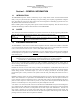
PS Engineering PMA8000B Audio Selector Panel and Intercom System Installation and Operator’s Manual Section I – GENERAL INFORMATION 1.1 INTRODUCTION The PMA8000B represents another evolutionary step in cockpit audio control and intercommunications utility. Using our patented IntelliVox® design, front panel utility jack, and pilot programmable configurations, this marks the next level of audio control. The unit is designed for outstanding ergonomics and visually defined mode annunciation and selection.
PS Engineering PMA8000B Audio Selector Panel and Intercom System Installation and Operator’s Manual A 3-light, 75 MHz Marker Beacon receiver is integrated in the PMA8000B. This provides the necessary Marker Beacon lights and audio indications necessary for that portion of an Instrument Landing System (ILS) approach. A pushbutton labeled MKR allows the pilot select high or low sensitivity as well as test and mute modes. 1.4 APPROVAL BASIS FAA TSO Approval.
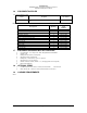
PS Engineering PMA8000B Audio Selector Panel and Intercom System Installation and Operator’s Manual Audio Selector Specifications Audio selector panel input impedance: 510 Ω Input Isolation: -60 dB (min.) Speaker Muting: -60 dB (min.) Speaker Output (into 4 Ω) with no clipping 3 Watts (min.) 14 VDC: 10 Watts (min.
PS Engineering PMA8000B Audio Selector Panel and Intercom System Installation and Operator’s Manual 1.6 EQUIPMENT SUPPLIED 1 ea. of the following units: Model PMA8000B Description Part Number PMA8000B Audio Panel with Marker Beacon and Stereo intercom. 050-890-0202 PMA8000B Installation Kit: 250-890-0000 Description 1.
PS Engineering PMA8000B Audio Selector Panel and Intercom System Installation and Operator’s Manual Section II - INSTALLATION 2.1 GENERAL INFORMATION 2.1.1 SCOPE This section provides detailed installation and interconnection instructions for the PS Engineering PMA8000B Audio Selector Panel/Intercom/ with internal Marker Beacon. Please read this manual carefully before beginning any installation to prevent damage and post-installation problems.
PS Engineering PMA8000B Audio Selector Panel and Intercom System Installation and Operator’s Manual 2.3.4 Audio Panel Tray and Connector Assembly The rack connectors mate with two 44-pin connectors in the PMA8000B. The connectors are a subminiature crimp-type, and require the use a hand crimp tool, from table below (or equiv.). The connectors are mounted to the tray back plate with #4-40 screws (475-440-1038), from the inside of the tray and the mounting block, 431-891-0100.
PS Engineering PMA8000B Audio Selector Panel and Intercom System Installation and Operator’s Manual 2.4.1.1 Music Inputs and Noise PMA8000B units above Serial Number J01861 utilize a differential input to help prevent noise from entering the music system. This feature is usually transparent to the installer, however, it is important that the appropriate music signal and ground connections are made directly to the dedicated music signal and ground inputs on the PMA8000B.
PS Engineering PMA8000B Audio Selector Panel and Intercom System Installation and Operator’s Manual 2.4.5.1 Speaker Load The PMA8000B contains one speaker amplifier. Some units with internal speaker amplifiers, such as the King Radio KX170-series, require a resistive load to prevent damage if their speaker amplifier is not used. Connect the speaker output from the unit to the COM 2 Speaker load input on the PMA8000B (J1 27 WRT 28). The speaker load is 16 Ω, 3W. 2.4.
PS Engineering PMA8000B Audio Selector Panel and Intercom System Installation and Operator’s Manual yoke to change transceivers. The transfer of TX indication from Com 1 to Com 2 shows that the swap has been initiated; there is no dedicated swap indicator. 2.4.9 Backlighting The PMA8000B has an automatic dimming of the pushbutton annunciation LEDs and marker lamps controlled by a photocell.
PS Engineering PMA8000B Audio Selector Panel and Intercom System Installation and Operator’s Manual 2.4.11 Public Address Mode By pressing the Mute and SPR pushbuttons at the same time, the PMA8000B will be placed into public address (PA) mode. In this mode, the pilot will be talking over the cockpit speaker when he presses his PTT switch . Copilot will still continue on the selected COM radio.
PS Engineering PMA8000B Audio Selector Panel and Intercom System Installation and Operator’s Manual Any signal appearing in the hard wired unswitched audio inputs will always mute the entertainment sources, even though the passengers may not hear the audio tone itself. Press the Mute switch to activate the Karaoke mode (disabling crew SoftMute™), This allows the pilot to place the entertainment into the background while having the radios in the foreground.
PS Engineering PMA8000B Audio Selector Panel and Intercom System Installation and Operator’s Manual 2.6.2 External Marker Lights For installations that require external marker beacon lights, there are three outputs that can drive 12-Volt lamps only. The external output lamps are driven high (typically +9 VDC ±1.5 VDC unloaded, at MAX brightness) when active. Maximum source current per lamp is 125 mA. Voltage varies with photocell dimming. 2.6.
PS Engineering PMA8000B Audio Selector Panel and Intercom System Installation and Operator’s Manual Figure 2-3 – Unswitched 3 Audio Level (bottom cover removed) 2.8 Communications Antenna Installation Notes For best results while in Split Mode, it is recommended that the one VHF communications antenna is located on top of the aircraft while the other communications antenna is installed on the bottom. Any antenna relocation must be accomplished in accordance with AC 43.
PS Engineering PMA8000B Audio Selector Panel and Intercom System Installation and Operator’s Manual 2.
PS Engineering PMA8000B Audio Selector Panel and Intercom System Installation and Operator’s Manual 2.10 Post Installation Checkout After wiring is complete, verify power is ONLY on pins 8 and 9 of the J2 and airframe ground on connector pins 10 and 11. Failure to do so will cause serious internal damage and void PS Engineering's warranty. 2.11 Unit Installation To install the PMA8000B, gently slide the unit into the mounting rack until the hold-down screw is engaged.
PS Engineering PMA8000B Audio Selector Panel and Intercom System Installation and Operator’s Manual 13. Push the SPR button. Verify that all selected audio is heard in the cockpit speaker. Verify that the audio mutes when the mic is keyed. 14. Verify that the appropriate LED in the lower button row blinks when either push to talk is keyed. 15. Verify proper Intercom system operation in the ALL, ISO and CREW modes (see Table 3-1). 16.
PS Engineering PMA8000B Audio Selector Panel and Intercom System Installation and Operator’s Manual found in Appendix F. Return completed warranty registration application to PS Engineering, or complete online at www.ps-engineering.com.
PS Engineering PMA8000B Audio Selector Panel and Intercom System Installation and Operator’s Manual Section III OPERATION 3.1 SCOPE This section provides detailed operating instructions for the PS Engineering PMA8000B, Audio Selector Panel/Marker Beacon Receiver/Intercom Systems. Please read it carefully before using the equipment so that you can take full advantage of its capabilities. This section is divided into five sections covering the basic operating areas of the PMA8000B systems.
PS Engineering PMA8000B Audio Selector Panel and Intercom System Installation and Operator’s Manual switched off. In essence, switching the mic selector will not override prior selection of COM receiver audio. In normal (not split) modes, the PMA8000B gives priority to the pilot’s radio Push-To-Talk (PTT). If the copilot it transmitting, and the pilot presses his PTT, the pilot’s microphone will be heard over the selected com transmitter.
PS Engineering PMA8000B Audio Selector Panel and Intercom System Installation and Operator’s Manual NOTE Because the cell-phone uses an intercom circuit, all stations on that circuit will lose intercom capability when the cell phone is in use. 3.5 Speaker Amplifier (5) The SPR in the lower right section stands for speaker. This switch will place all selected audio on the cockpit speaker when this switch is selected.
PS Engineering PMA8000B Audio Selector Panel and Intercom System Installation and Operator’s Manual pled. Non-voice signals are blocked. When someone speaks, only their microphone circuit opens, placing their voice on the intercom. The system is designed to block continuous tones; therefore people humming or whistling in monotone may be blocked after a few moments. For consistent performance, any headset microphone must be placed within ¼-inch of your lips, preferably against them. (ref: RTCA/DO-214, 1.3.
PS Engineering PMA8000B Audio Selector Panel and Intercom System Installation and Operator’s Manual 3.7.3 Intercom Modes (8) The “ICS” pushbutton switch on the left side of the panel provides the selection of the three intercom modes. The description of the intercom mode function is valid only when the unit is not in the "Split" mode. Then, the pilot and copilot intercom is controlled with the Mute button.
PS Engineering PMA8000B Audio Selector Panel and Intercom System Installation and Operator’s Manual NOTE Because the cell phone uses an intercom circuit, all stations on that circuit will lose intercom capability when the cell phone is in use. PS Engineering does not guarantee compatibility with personal cellular telephones. Visit www.ps-engineering.com for a list of phones that have been tested. 3.10 Utility Jack The 2.
PS Engineering PMA8000B Audio Selector Panel and Intercom System Installation and Operator’s Manual 3.10.4 Smart Function Keys (SFK) With Virtual Tech Support, the configuration process is self-directed. Once you’ve set up your system, you don’t need to change it again, unless you want to. The unit will always remember your settings. SFK annunciations are heard by the pilot and copilot positions only. SFK annunciations will be heard by the copilot, even when the audio panel is in pilot isolate mode.
PS Engineering PMA8000B Audio Selector Panel and Intercom System Installation and Operator’s Manual These functions are non-essential and non-required and as such are only an accessory capability. They don’t affect the audio panel’s primary function as a selector panel, aircraft intercom, or marker beacon receiver. You can’t do anything with these buttons to prevent the PMA8000B from doing its main job.
PS Engineering PMA8000B Audio Selector Panel and Intercom System Installation and Operator’s Manual When “Music one all headsets” is selected, music 1 (or the front panel utility jack) will be distributed to all headsets and is independent of the intercom mode switch. Therefore, even in the CREW mode, the passengers will hear Music 1, even though they will not hear the intercom or radios.
PS Engineering PMA8000B Audio Selector Panel and Intercom System Installation and Operator’s Manual Passengers Music 2 Passengers Music 2 Passengers Music 2 ICS ICS Copilot Pilot & Copilot Music 1 Pilot & Copilot Music 1 Music 1 Pilot Music Distribution Standard All Mode Music Distribution Standard ISO Mode Music Distribution Standard Crew Mode Figure 3-4 Standard Music Distribution When the music is standard, Music 1 will always go to the pilot and copilot positions, and is never heard by the
PS Engineering PMA8000B Audio Selector Panel and Intercom System Installation and Operator’s Manual Section IV – Warranty and Service 4.1 Warranty In order for the factory warranty to be valid, the installations in a certified aircraft must be accomplished by an FAA-(or other ICAO agency) certified avionics shop and authorized PS Engineering dealer.
PS Engineering PMA8000B Audio Selector Panel and Intercom System Installation and Operator’s Manual Appendix A – External PTT Hook Up Part of the installation includes the installation of PTT (Push To Talk) switches that allow the use of your aircraft radio for communications transmissions. There are three possible configurations ; you must select the case that best fits your installation. NOTE: Only the person who presses their PTT switch will be heard over the radio.
PS Engineering PMA8000B Audio Selector Panel and Intercom System Installation and Operator’s Manual Appendix B – PMA 8000 Installation Drawings 475-013-0001 Lock nut (4 ea) 44-pin connector (2 ea) 475-440-0004 (4 ea) 475-440-0007 (4 ea) Rack back plate 430-890-0050 Rack 430-890-0040 J2 J1 Viewed from Back 15 30 44 15 30 44 1 16 31 1 16 31 Solder Lug (mount as convenient) Rear plate detail (not to scale) 6.31in 1.28in 1.28 in 0.96in 0.36in 0.37in 3.87in 5.53in 6.
PS Engineering PMA8000B Audio Selector Panel and Intercom System Installation and Operator’s Manual Appendix C – J1 Connector Interconnect Com 1 Audio Hi Com 1 Lo Communications Transceiver #1 Com 1 Mic Audio Hi Com 1 Mic Key Com 2 Audio Hi Communications Transceiver #2 Com 2 Lo Com 2 Mic Audio Hi Com 2 Mic Key See Note 4 Com 2 SPR Load Com 2 Spr Load Com 2 Spr Load TEL Audio Hi TEL Audio Lo Telephone TEL Mic Audio Hi Nav 1 Audio Hi VHF Nav 1 Nav 1 Audio Lo VHF Nav 2 See Note 6, 10 & 11 ADF
PS Engineering PMA8000B Audio Selector Panel and Intercom System Installation and Operator’s Manual Appendix D – J2 Connector Interconnect PMA8000B J2 CONNECTOR (Sub-D 44-pin male on tray) 31 16 1 Pilot Phones (R) Pilot Phones Lo 4 3 2 Copilot Phones (R) 15 Unswitched Input #4 Hi Unswitched Audio Lo Note 13 Pass. Mic Hi Pass. 1 Mic Jack Pass. Mic Lo Pass. Mic Hi Pass. 2 Mic Jack Pass. Mic Lo Pass. Mic Hi Pass. 3 Mic Jack Pass. Mic Lo Pass. Mic Hi Pass. 4 Mic Jack Pass.
PS Engineering PMA8000B Audio Selector Panel and Intercom System Installation and Operator’s Manual Appendix E – Instructions for FAA Form 337 and continuing airworthiness 9.1 Instructions for FAA Form 337, Audio Panels One method of airworthiness approval is through an FAA Form 337, Major Repair and Alteration (Airframe, Powerplant, Propeller, or Appliance) In the case of the PMA8000B, you may use the following text as a guide.
PS Engineering PMA8000B Audio Selector Panel and Intercom System Installation and Operator’s Manual Appendix F – RTCA DO160D Environmental Qualification Form Audio Selector Panel/Intercom/Marker Beacon Receiver Part Number: 050-890-( ) FAA TSO Number: C50c, C35d Manufacturer: PS Engineering Incorporated 9800 Martel Road Conditions Temperature and Altitude Low Temperature High Temperature In-flight Loss of Cooling Altitude Decompression Overpressure Temperature variation Humidity Shock Operational Crash Saf