
Specifications


PS Engineering
PMA8000B Audio Selector Panel and Intercom System
Installation and Operator’s Manual
200-890-0100 Page 2-6 Revision 8, May 2008
2.4.11 Public Address Mode
By pressing the Mute and SPR pushbuttons at the same time, the PMA8000B will be placed into public
address (PA) mode. In this mode, the pilot will be talking over the cockpit speaker when he presses his
PTT switch . Copilot will still continue on the selected COM radio.
To enable the PA Digital Output located at the rear connector, the internal configuration jumper, J4, MUST
be placed across both pins in the header. This jumper is shipped as open from the factory. Contact PS En-
gineering for details on changing this configuration jumper.
When this Digital Output is enabled, J2 Pin 19 will go low when in PA mode, providing a logic level that
can be used to incorporate a speaker-switching scheme. This 50 mA circuit (10Ω Z) can control a switch-
ing means such as a relay that would transfer the speaker output amplifier from the cockpit speaker to drive
another cabin speaker. If the PA mode is used with a microphone in proximity to an active cockpit speaker,
feedback might result.
2.4.12 PA Mute (J2, Pin 12)
Pin 12 of J2 is a TTL logic output that is pulled low during PTT operation. This serves as an input to exter-
nal public address system to prevent feedback during transmissions.
2.4.13 Miscellaneous Logic Output (J2, Pin 18)
Pin 18 of the J2 connector is pulled to ground whenever the AUX button is depressed. This serves as a
control line for external devices, such as an entertainment system that the pilot wishes to control.
This pin can also be used to control passenger Karaoke Mode, by connecting to pin 13 of the J2, or as a PA
cockpit/cabin speaker relay control.
NOTE
J2, Pin 18 should NOT be used if the AUX is going to be used to switch DME or auxiliary audio.
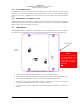
2.5 Intercom wiring
See Appendix C and D for intercom connection configurations. It is critical to the proper operation of this
system to have this connector wiring made in accordance with these diagrams. Use 2- and 3-conductor,
MIL-spec cable as shown. Connect the shields at the audio panel end only, and tie to the audio low inputs
as shown.
NOTE
The intercom harness can be custom made by PS Engineering, Inc. Simply call the factory or www.ps-
engineering.com to obtain a wire harness work sheet. The harness will be made to your specifications and
fully functionally tested. Harness can be ordered with jack, or without the intercom jacks installed, for eas-
ier wire routing through the aircraft.
2.5.1 Entertainment Inputs
The PMA8000B has two INDEPENDENT music inputs, PLUS a front mounted jack that is connected to
Entertainment 1. Entertainment input number 1 is J2 pins 23 (left channel) and 24 (right channel), with
respect to pin 25, and Entertainment number 2 is connected to 26 (left channel), 27 (right channel), with
respect to 28.
NOTE
Use the low level output of any additional entertainment device to connect to the au-
dio panel. Maximum signal level is 3 VAC p-p. DO NOT use a speaker-level output,
this will cause internal damage in the audio panel.
2.5.2 Entertainment muting
The PMA8000B-system incorporates a "Soft Mute™" system. This will mute the entertainment devices
during ICS or radio conversation.