
user manual


3URGXFW5HIHUHQFH*XLGH A-1
$SSHQGL[ $
/('%HHSHU,QGLFDWLRQV&RQWUROV
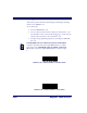
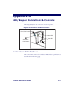
Figure A-1 shows the operator’s controls and indicators. The descriptions
following identify the use or function of each component.
)LJXUH $6FDQQHUDQG6FDOH&RQWUROV
&RQWUROVDQG,QGLFDWRUV
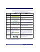
The control panel consists of two indicator LEDs and two push buttons as
described in the following pages.
Green LED
Yellow LED
Scale Zero
Push Button
Volume/Tone Push Button