User’s / Programming Guide Bar Code S Handheld Laser Bar Code Scanners Keyboard Wedge / Wand Emulation Interface PSC INC.
If you have any questions or need assistance after reading this manual, please contact PSC Customer Service at: PSC Inc. 675 Basket Road P.O. Box 448 Webster, New York 14580-0448 Telephone: 716-265-1600 800-828-6489 Fax: 716-265-6400 The descriptions and specifications herein were in effect at the time of manual production. Every effort was made to make the information complete and correct.
Scanners discussed in this manual are covered by patents issues or pending in the U.S. and other countries. NOTICE The scanner is certified to be a Class II laser product with the United States Department of Health and Human Services Center for Devices and Radiological Health. NOTICE The scanner, as a component, has been tested for compliance with the EMI requirements of the United States Federal Communications Commission Part 15, Sub-Part J, Class A.
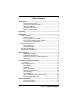
Table of Contents Introduction...................................................................................... Keyboard Wedge Mode........................................................ Serial Communications Mode............................................... AutoSense® Mode ............................................................... Wand Emulation Mode ......................................................... Magnetic Stripe Reader........................................................
System Status .................................................................... Power Consumption........................................................... Laser Redundancy ............................................................. Laser Timeout .................................................................... Beeper Operation............................................................... 22 23 23 24 24 Message Formatting ....................................................................
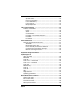
Memory Module ............................................................................. 62 Setup......................................................................................... 63 Marker Beam .................................................................................. 64 Scanner Labeling........................................................................... 66 Service and Warranty ......................................................... 66 Maintenance ................................
Introduction Keyboard Wedge Mode As a keyboard wedge interface, the PSC scanner can be used with terminals provided by most of the major terminal manufacturers. In most cases, the PSC scanner is easily connected between the keyboard and display of the terminal. The use of Preamble/Postamble, embedded keyboard function codes or keyboard function records allow operation of the terminal without manual entry from the keyboard. In this mode of operations, the PSC scanner draws power from the terminal.
Unpacking Your package should include a scanner, interface cable, User’s Manual, and a plastic scanner holder. The unit should be inspected immediately upon receipt to determine if any damage has occurred during shipment. If damage has occurred, a claim should be filed with the carrier immediately. Retain the shipping box, since it should be used to return the scanner to the factory for service. Installation Keyboard Wedge In Keyboard Wedge mode the PSC scanner simulates keyboard keystrokes.
Connecting the Power Supply If supplied, plug the connector from the external power supply into the receptacle located on the housing connector. Then plug the power supply into a power source. Connecting a Magnetic Stripe Reader If a detached Magnetic Stripe Reader (MSR) is to be used, plug the connector into the MSR receptacle located on the housing connector. Terminal Power-Up Sequence Turn on the power to the terminal to which the PSC scanner is connected.
Serial Communications The PSC scanner provides the user with two different serial communications options: Serial TTL and Serial RS232 communications. Serial TTL Mode Serial TTL is a serial communications interface that uses TTL/CMOS voltage levels ranging from 0 to 5 volts. The user can select a normally high (default setting) or normally low (inverted) voltage levels. Serial TTL communications mode uses different cables than those used in keyboard wedge applications.
AutoSense® Operation AutoSense® is a factory installed feature requested at time of order. It provides for hands-free or handheld operation. AutoSense® is activated by scanning the Enable AutoSense® symbol. The scanner will respond by emitting a continuous, low level red beam of light known as the trigger beam. AutoSense® is deactivated by scanning the Disable AutoSense® symbol.
NO Enable AutoSense® NN Disable AutoSense® To use this mode of operation properly, the user must first attach the plastic scanner holder to the bracket of the stand as shown in Figure 1. The (NO) Enable AutoSense® programming symbol is scanned until the green “Good Decode” light blinks. This will activate the trigger screen. The scanner is then placed into the holder and the user must check that the red laser beam is aimed at the reflective label affixed to the stand.
Wand Emulation Operation To operate the PSC scanner in Wand Emulation the user must first turn off the powerto the host device and then detach the scanner from the host device by removing the cable from the scanner. The proper Wand Emulation cable must be connected between the scanner and the portable data terminal for remote data collection. If using an optional Smart Cable, the scanner automatically switches to Wand Emulation. Specific Wand Emulation parameters may still need to be set.
Setup Overview General setup parameters are divided into Keyboard Wedge options (communication to host through the terminal keyboard), Wand Emulation options (communication between the scanner and the host system’s decoder), and Serial Communication options (communications direct to the host system). Default options are denoted throughout the manual as follows: — Keyboard Wedge @ — Wand Emulation # — Serial Communication * Wedge Mode Options Several wedge mode options are available.
Data Synchronization • Disable Data Synchronization • Enable Data Synchronization • Active Polarity High • Active Polarity Low Serial Communication and Wedge Options The following communication options are used to define how your PSC scanner communicates with the host system through its serial interface or its keyboard wedge interface.
Symbologies The bar codes that can be read by PSC’s bar code scanners include: Code 39 Code 93 Interleaved 2 of 5 Code 128 Standard 2 of 5 Codabar UPC-A, UPC-E Code 11 EAN/JAN MSI/Plessey A complete list of the related options and the instructions for setting them are provided in the section on Symbologies. NOTE 10 Scanning problems are most often caused by poor quality bar code symbols.
Parameters Selection Guidelines Three basic steps must be followed when selecting parameters for your scanner. 1. Review this manual to be sure you understand the terminology. 2. Review the requirements of your host system, with a technical expert from your company, if necessary. This will enable you to determine if any of the factory default settings must be altered. 3. Enable or disable the relevant parameters by scanning the appropriate menus.
1. Scan the bar code beside Intercharacter Delay = XX and listen for one short-high beep. 2. After the beep, scan the bar code beside 0 on the Digit Selection page and listen for one short-high beep. 3. Still at the Digit Selection page, scan the bar code for 5 (the last argument in the command) and listen for two short beeps. Your PSC scanner does not have a distinct programming mode. Instead, it automatically recognizes and reacts to the labels you scan.
Serial Communication Reset Default To program the communication mode for serial asynchronous communication, scan the following label: CA Select Serial Output Baud Rate There are seven standard serial communication baud rates to select from. Your scanner and the serial host computer must be set to the same baud rate. Select the correct rate.
Data Transmission Serial transmission data is composed of three of four different elements, depending upon host system requirements. These elements are the START bit, DATA bits (7 or 8 bits), OPTIONAL PARITY bits, and STOP bit (s) (1 or 2 bits). The PARITY bit is used for error detection (e.g., data altered in transmission), but is not required by all systems.
Table 1. 7 Bit Options Data Stop Bits 7 2 Mark EF 7 2 Space EE Parity Option If your system requires a WORD length of 8 bits, 1 or 2 STOP bits, and PARITY check, select the appropriate option from the table below: Table 2.
If your system requires a WORD length of 8 bits and 1 or 2 STOP bits, but no PARITY, select the option below: Table 3. 8 Bit, No Parity 8 1 8 2 None EM EN PARITY check is not possible with this combination of STOP bits and WORD length. Some receiving equipment requires inverted serial communication signals. CD Inverted Serial Communications Communications Protocol XON/XOFF Protocol controls data flow between your PSC scanner and a serial host computer.
CTS Like XON/XOFF protocol, CTS protocol is a mechanism used to control data flow out. The CTS input is used to inform the scanner that the host terminal is ready to accept scanned data. When CTS (+) protocol is selected, the scanner waits for a low level on its CTS input before transmitting data. When CTS (-) is selected, the signal polarities are reversed and a high level indicates data may be transmitted.
HD Protocol = CTS (+) HG RTS always low HH RTS always high HI RTS high indicates scanner ready to receive data HJ RTS low indicates scanner has data to transmit HK RTS high indicates scanner has data to transmit Another flow control option is available. If enabled, the stop/go protocol disables the trigger after every successful scan. The trigger is then re-enabled with a serial ‘BG’ command in format BG.
Label Buffering The user may select one of three levels of serial buffering. With Full Buffering (the default) selected, the scanner will place all scanned labels into a buffer for transmission. This allows the operator to continue scanning even though the previous label may not have been transmitted yet. Scanning will continue normally until the buffer is full, then scanning will stop. Scanning will continue when enough space is available for the current label.
Menu Commands Parameter Messages In serial mode, most menu commands when scanned will provide a confirmation message to the host along with the ACK. This feature can be enabled or disabled. BA Enable Parameter Messages * BB Disable Parameter Messages External Trigger Operation External trigger operation enables an external device to control scanning. External trigger is controlled by applying an external trigger signal to the CTS input (with external triggering enabled).
HF External Trigger(-) General Parameters Intercharacter Delay Certain terminals and computers require an intercharacter delay to simulate the effects of keystroke delays. Choosing an intercharacter delay causes the characters to be sent at the slower speed required by the device to which you are interfacing. GA No Intercharacter Delay NOTE GB To set Intercharacter Delay to other then zero, scan the label below and then scan two separate digits from the Digit Selection page (99 maximum).
Transmission Mode Full Duplex or Half Duplex This section pertains only to models with a Liquid Crystal Display (LCD) NOTE Transmission mode selects either full or half duplex operation regardless of interface. In the half duplex mode, the decoded message is sent simultaneously to the display and to the host computer. In the full duplex mode, the message is sent to the host computer. In send mode, the host always has the capability to send a message directly to the LCD.
ZB Display Configuration When Option ZC is scanned, the program version followed by carriage return-line feed characters (CR-LF) is sent in the format SP<###> (WDHB 3.86, for example). ZC Transmit Version Number Power Consumption You may choose one of two Power Consumption modes. Option @A supplies full power to the scanner at all times; Option @B allows the unit to revert to a standby mode after a successful read. This mode is a power conservation feature.
BE Enable 4 Times Laser Redundancy Laser Timeout The scan beam will activate in response to a trigger pull. The beam will automatically deactivate after a label is decoded. If a label is not decoded., the scan beam will timeout and deactivate after several seconds. Scan the following labels to control the length of the timeout.
AC Beeper On; Volume Medium AD Beeper On; Volume Loud *#@ Message Formatting Message formatting describes how to format the data (decoded string) that is sent from the scanner to the host. The programmable options DO NOT apply in Wand Emulation. NOTE Prefixes and Suffixes Prefix Terminal ID Preamble Code ID Data Postamble Suffix Prefixes, Suffixes, Preambles and Postambles are programmable attributes that are transmitted along with the decoded label data to the host device.
Prefix A prefix is a subset of the preamble normally formatted to some industry standard, i.e., it is represented by a specific ASCII code. An example of a prefix is the STX (Start of Transmission) code. IA Prefix = None*# IB Prefix = STX IC Prefix = SOH Suffix A suffix is a subset of the Postamble. Like the prefix, it is normally assigned a specific ASCII code. Examples of suffixes are CR (Carriage Return) and LF (Line Feed).
MF Suffix = CR and LF * Users also have the ability to select any ASCII character for use as a suffix. Scan the MJ label, then scan two labels from the Hexadecimal Conversion Table representing the character needed for the suffix. MJ Select Programmable Suffix Character Certain specialized applications require a two character suffix of ETB NUL. Scanning MI provides this.
Code Identifier A code identifier may optionally be transmitted with the message. This option is provided so a host computer can identify the type of bar code scanned, as well as the encoded information. Scan Option FA to disable the code identifier. FA Disable Code ID # * Scan Option FB to enable the code identifier. FB Enable Code ID The table below shows the default code-identifier character assignments. These can be changed using the procedure found in the Symbology Identifier Section. Table 4.
Preamble or Postamble Selection Preambles and Postambles are composed of up to four ASCII characters. Each ASCII character is encoded as two hexadecimal numbers. Use the Hexadecimal Conversion Table in Appendix A to look up the hexadecimal equivalent. NOTE If you select a Preamble or a Postamble you must scan four ASCII characters, even if the Preamble or Postamble is less than four characters in length. This is done by scanning in null (NUL) characters for the additional characters.
LA Postamble = None*# LB Enter Postamble IMPORTANT Scan Enter Postamble to enter a Postamble, then refer to the Hexadecimal Table in Appendix A.
Serial Commands General Serial Command Format Serial Commands are only accepted by the PSC scanner when in serial communications mode. Serial commands take the form: STX ESC LT1 LT2 ETX (Note: STX = ^B; ETX = ^C) STX, ESC, and ETX are ASCII codes whose values are 02H, 1BH, and 03H, respectively. LT1 and LT2 are uppercase ASCII letters (commercial A and @ are the same as those printed in earlier sections of this manual under their corresponding menu bar code labels).
Beeper Off CR-LF Ack If the scanner receives an unknown or improperly formatted code, or if the required parameters are missing or out-of-range, it sends a NAK (15H) Code.
Power Standby and Serial Commands When the scanner is programmed for standby power operation (@B), the first character of the command is used to “wake-up” the scanner; it is not properly received by the scanner’s CPU. Therefore, when there is any possibility that the scanner is in standby mode, an extra space code should be transmitted before STX to ensure the scanner is “awake” before sending commands to it.
Keyboard Wedge Parameters Scan symbol CE to enable Keyboard Wedge mode. Next, select a terminal type by scanning the symbol CF for IBM PC-AT or PS/2 models 50/60/80; or symbol CG for PC-XT type terminals. Alternatively, you may scan just CF or CG to enable wedge mode and select a terminal type. CE Wedge Mode Enable @ ZA Reset to Wedge Default Values CF PC-AT, PS/2 and 50/60/80@ — U.S.A. CG PC-XT – U.S.A. CH IBM 3151 – U.S.A. CI DEC VT220 – U.S.A. CN Macintosh CP IBM 3477 – U.S.A.
CT IBM 319X – U.S.A. CY PS/2 Mode 57/25 — U.S.A.
\E PC-AT Italian Keyboard \F PC-AT Spanish Keyboard \G PC-AT Swedish Keyboard \H PC-AT Portuguese Keyboard \L DEC VT 220/320/420 German Keyboard \M DEC VT 220/320/420 French Keyboard In normal Wedge Mode, the scanner emulates the keyboard exactly. Should a scanned bar code label have alphabetic characters, they will be presented to the computer as if they had been typed at the keyboard. They will be affected by the Caps Lock key.
EO Shift Alphabetic Characters EP Normal Alphabetic Characters* NOTE In some models of scanner, the wedge output is capable of two types. To enable primary or secondary keyboard modes, scan one of the next two labels. CQ Enable Primary Keyboard@ CR Enable Secondary Keyboard NOTE In Wedge Mode, non-printable ASCII characters (00-31H) do not allow for an obvious translation to keycodes. There are two approaches to this issue – they are explained in Appendix A.
Symbologies The PSC scanner is configured with Code 39, Code 128, UPC-A and UPC-E not expanded symbologies. The user has the ability to enable or disable any of the symbologies given below as well as UPC or EAN supplements, I 2 of 5 with check digit, and Code 39 modulo 43 check digit.
Option QB or Option QC enable both UPC-A and UPC-E. If UPC is enabled, any UPC label, with or without supplement, is read. The supplement is read if Option QB is selected, and it is ignored if Option QC is selected. QB Enable UPC with 2 or 5 Digit Supplement Enabled QC Enable UPC with 2 or 5 Digit Supplement Disabled *#@ Expanded UPC-E is disabled by scanning Option QH, or is enabled by scanning Option QI.
Transmission of the last character in a UPC symbol (the check digit) is disabled by scanning Option QF, or is enabled by scanning Option QG. QF Disable Transmission of Check Digit QG Enable Transmission of Check Digit *# Scanning QJ causes UPC-A labels to be transmitted as EAN-13 labels. Scanning QK disables this feature.
QS Enable transmissionof UPC-E check digit* QT Disable transmission of UPC-E number system digit QU Enable transmission of UPC-E number system digit QV Disable UPC-E* QW Enable UPC-E independently with supplement QX Enable UPC-E independently without supplement* Q0 Disable mandatory supplements* Q1 Enable mandatory supplements QA to QG apply to UPC-A and UPC-E.
EAN/JAN Scan Option RA to disable EAN/JAN (8 or 13 digit). RA Disable EAN/JAN (8 or 13 Digit) #@ Option RB or RC enables both EAN 8 digit and EAN 13 digit. If EAN/JAN is enabled, any EAN/JAN label, with or without supplement, is read. The supplement is read if Option RB is selected and is ignored if Option RC is selected.
Transmission of the last character in an EAN/JAN symbol (the check digit) is disabled by scanning Option RF, or is enabled by scanning Option RG.
RQ Disable EAN-8 special 5 character (0’s) preamble RR Enable EAN-8 special 5 character (0’s) preamble RA to RG apply to both EAN-13 and EAN-8. NOTE Code 39 To disable Code 39, scan Option OA. OA Disable Code 39 To enable Code 39, scan Option OB or OC. After enabling Code 39, make any additional required selections from Options OD through OG.
The minimum length of Code 39 messages is set by scanning Option OH, followed by scanning two digits (01-32) from the Digit Selection page. OH Minimum Length (specified by two digits 01-32) The maximum length of Code 39 messages is set by scanning Option OI, followed by scanning two digits (01-32) from the Digit Selection page. If the minimum and maximum values are set equal, only codes of that exact length are read.
Code 2 of 5 – Interleaved Scan Option PA to disable Interleaved Code 2 of 5. PA Disable Interleaved Code 2 of 5*#@ Scan Option PB or PC to enable Interleaved Code 2 of 5. PB Enable Interleaved 2 of 5 without Check Digit PC Enable Interleaved 2 of 5 with Check Digit The minimum length of Interleaved 2 of 5 messages is set by scanning Option PD, followed by scanning two digits (02-32) from the Digit Selection page. The value of the number you scan must be even.
Code 2 of 5 – Standard Scan Option PF to disable Standard Code 2 of 5. PF Disable Standard Code 2 of 5 *#@ Scan Option PG to enable Standard Code 2 of 5. PG Enable Standard 2 of 5 The minimum length of Standard 2 of 5 messages is set by scanning Option PH, followed by scanning two digits (01-32) from the Digit Selection page. The maximum length is set by scanning Option PI, followed by scanning two digits (01-32) from the Digit Selection page.
Code 128 Scan Option TA to disable Code 128. TA Disable Code 128 Scan Option TB to enable Code 128. TB Enable Code 128 *#@ The minimum length of Code 128 messages is set by scanning Option TC, followed by scanning two digits (01-32) from the Digit Selection page. TC Minimum Length (specified by two digits 01-32) The maximum length of Code 128 messages is set by scanning Option TD, followed by scanning two digits (01-32) from the Digit Selection page.
The minimum length of Codabar messages is set by scanning Option VE, followed by scanning two digits (01-32) from the Digit Selection page. VE Minimum Length (specified by two digits 01-32) The maximum length of Codabar messages is set by scanning Option VF, followed by scanning two digits (01-32) from the Digit Selection page. If the minimum and maximum values are set equal, only codes of that exact length are read.
MSI/Plessey Previous customization of other scanner features may have made MSI/Plessey unavailable in some scanners. Consult Customer Service for current capabilities or if you require a specific symbology. PK Enable MSI/PLESSEY PL Set Minimum Length, then scan two digits: 01-14 (see Digit Selection). PM Set Maximum Length, then scan two digits: 01-14 (see Digit Selection).
SF Set Minimum Length, specified by two digits 01-32 SG Set Maximum Length, specified by two digits 01-32 SE Enable transmission of check digits SD Disable transmission of check digits SA Disable Code 11 Code 93 Previous customization of other scanner features may have made Code 93 unavailable in some scanners. Consult Customer Service for current capabilities or if you require a specific symbology.
UD Enable Full ASCII Code 93 UE Set Minimum Length, specified by two digits 0-1-32 UA Disable Code 93 16K TF Enable 16K Code TE Disable 16K Code 52 User’s / Programming Guide
Digit Selection 5 0 6 1 7 2 8 3 9 4 06656 53
Symbology Identifiers Your PSC scanner can be programmed to add and/or change symbology identifiers which might be required to be transmitted with messages. This feature is provided to allow a host computer to recognize the type of bar code scanned, as well as the uncoded information. The symbology identifiers are selected by scanning the desired programming bar code symbol as defined below.
FJ Set Code 39 Symbology Identifier FK Set I 2/5 Symbology Identifier FL Set S 2/5 Symbology Identifier FM Set Code 11 Symbology Identifier FN Set Code 93 Symbology Identifier FO Set Codabar Symbology Identifier FP Set MSI/Plessey Symbology Identifier To change any single symbology identifier, scan the appropriate symbology identifier bar code symbol and then scan the four hexadecimal characters that represent the two bytes of the identifier.
To find the hexadecimal values for the characters turn to the Hexadecimal Conversion Table. The procedure for selecting a symbology identifier is identical to the procedure for selecting Preambles and Postambles. The similar difference is that symbology identifiers are a maximum of two characters, not four. NOTE Scanning the ZA (Result to Default) programming symbol will set all symbology identifiers back to PSC defaults as given in Table I and disable the transmission of the symbology identifiers.
Table 5.
Wand Emulation Parameters Select Code Type Scan Option CC if you intend to operate the scanner in Same Code Wand Emulation mode. If you want the label to be transmitted in Code 39 scan Option CB. CC Same Code Wand # Emulation CB Wand Emulation (Code 39, Full ASCII) Bar Code Polarity Selected Option WA or WB.
YB 10 inches per second# YC 15 inches per second YD 20 inches per second YE 30 inches per second YF 50 inches per second YG 70 inches per second 06656 59
Data Synchronization Your PSC scanner can be prepared to synchronize the transmission of scanned data to the timing sequence some terminals require to properly receive the data. This relationship is diagrammed in Figure 2. Figure 2. Timing Sequence Diagram Data Transmission data (ta) Active white space (th) Data Synchronization Setup Time (ts) 200 ms - 220 ms Hold Time (th) 0 ms - 10 ms RTS output is used for the data synchronization signal. Scan XD to enable the data synchronization signal.
XE Active # Polarity High XF Active Polarity Low 06656 61
Memory Module The Memory Module option is a factory installed feature that is requested at time of order. The Memory Module option allows the 5300 series scanner to store decoded labels in an internal battery backed up RAM. The stored buffered labels can then be transmitted some time later. The user may also choose an interlabel transmission delay in cases where the transmission rate of the buffered decoded label is faster than the receiving equipment.
Setup NC Disable Memory Module*# ND Enable Memory Module MM Enable automatic switch to memory module MN Disable automatic switch to memory module * If enabled, this mode intelligently switches from POS mode to Memory Module mode based on power source.
Marker Beam The Marker Beam feature provides the user with a spotter beam for improved aiming at distant bar code labels and/or in extremely bright environments. You may also find a Marker Beam useful when scanning through showcase glass or bar code menus with labels in close proximity. This feature is available in all scanners without factory authorization. To activate the Marker Beam, the user must also program the duration of the Marker Beam.
300 ms 50 MS 350 MS 100 MS 400 MS 150 MS 450 MS 200 MS 500 MS 250 MS 06656 65
Scanner Labeling The PSC Laser Scanners use a low-power, visible laser diode. As with any bright light source, such as the sun, the user should avoid staring directly into the light beam. Use of controls, adjustments, or performance of procedures other than those specified herein may result in hazardous visible light exposure. WARNING Service and Warranty PSC provides service for its bar code products at the service center located at its manufacturing facility in Eugene, Oregon.
Maintenance PSC Scanners are designed to provide trouble-free operation throughout their lives. They contain no components that require periodic maintenance. Optimum performance may be ensured by following the preventive maintenance procedures suggested below. If scanning performance declines, please follow these procedures. Cleaning A dirty scan window can impair scanning performance. When the window appears to be dirty or smeared, clean it by wiping with a slightly damp cloth or facial tissue.
NOTES 68 User’s / Programming Guide
Appendix A Hexadecimal Conversion Table To use the conversion table: 1. Find each ASCII character in the tables on the following pages and locate the corresponding bold hexadecimal-equivalent character in the top row and in the left column of the table. Notice, for example, that the ASCII character “Q” is represented by the hexadecimal numbers 5 (top) and 1 (left). 2. Scan the bar code symbols that correspond to the hexadecimal-equivalent characters.
Hexadecimal Conversion Table Part A 0 0 1 2 0 1 2 3 NUL SOH STX ETX DLE DC1 DC2 DC3 SP ! “ # 0 1 2 3 4 5 6 7 EOT ENQ ACK BEL DC4 NAK SYN ETB $ % & ‘ 4 5 6 7 8 9 A B BS HT LF VT CAN EM SUB ESC ( ) * ++ 8 9 : ; C D E F FF CR SO SI FS GS RS US , .
Hexadecimal Conversion Table Part B 8 4 5 6 7 0 1 2 3 @ A B C P Q R S ‘ a b c p q r s 4 5 6 7 D E F G T U V W d e f g t u v w 8 9 A B H I J K X Y Z [ h i j k x y z { C D E F L M N O \ ] ^ _ l m n o | } ~ DEL 9 A B C D E F 06656 71
Primary Function Key Table ASCII NUL SOH STX ETX EOT ENQ ACK BEL BS HT LF VT FF CR SO SI DLE DC1 DC2 DC3 DC4 NAK SYN ETB CAN EM SUB ESC FS GS RS US 72 HEX 00 01 02 03 04 05 06 07 08 09 0A 0B 0C 0D 0E 0F 10 11 12 13 14 15 16 17 18 19 1A 1B 1C 1D 1E 1F FUNCTION CONTROL@ CONTROL A CONTROL B CONTROL C CONTROL D CONTROL E CONTROL F CONTROL G CONTROL H CONTROL I CONTROL J CONTROL K CONTROL L RETURN KEY CONTROL N CONTROL O CONTROL P CONTROL Q CONTROL R CONTROL S CONTROL T CONTROL U CONTROL V CONTROL W CONTROL X
Secondary Function Key Tables PC/AT, PC/XT, IBM 3151, and IBM PS/2 Model 57/25 ASCII NUL SOH STX ETX EOT ENQ ACK BEL BS HT LF VT FF CR SO SI DLE DC1 DC2 DC3 DC4 NAK SYN ETB CAN EM SUB ESC FS GS RS US HEX 00 01 02 03 04 05 06 07 08 09 0A 0B 0C 0D 0E 0F 10 11 12 13 14 15 16 17 18 19 1A 1B 1C 1D 1E 1F FUNCTION ESCAPE NEW LINE ENTER ALT left side Make ALT left side Break CTRL left side Make CTRL left side Break ENTER right keypad (NOTE 1) Cursor up (inner keypad) Cursor dn (inner keypad) Cursor left (inner ke
Secondary Function Key Tables IBM 3171/3181/3191 and IBM 3477 ASCII NUL SOH STX ETX EOT ENQ ACK BEL BS HT LF VT FF CR SO SI DLE DC1 DC2 DC3 DC4 NAK SYN ETB CAN EM SUB ESC FS GS RS US 74 HEX 00 01 02 03 04 05 06 07 08 09 0A 0B 0C 0D 0E 0F 10 11 12 13 14 15 16 17 18 19 1A 1B 1C 1D 1E 1F FUNCTION ESCAPE ON LINE ENTER (Make/Break) ALT left side Make ALT left side Break ON LINE ENTER (Make only) FIELD EXIT (Make only) ENTER right keypad Cursor up (inner keypad) Cursor dn (inner keypad) Cursor left (inner keyp
VT220/320/420 ASCII HEX NUL 00 SOH STX ETX EOT ENQ ACK BEL BS HT LF VT FF CR SO SI DLE DC1 DC2 DC3 DC4 NAK SYN ETB CAN EM SUB ESC FS GS RS US 01 02 03 04 05 06 07 08 09 0A 0B 0C 0D 0E 0F 10 11 12 13 14 15 16 17 18 19 1A 1B 1C 1D 1E 1F 06656 FUNCTION ‘~ (terminal may be configured for ESCAPE) NEW LINE ENTER – Return ALT Make ALT Break CTRL Make CTRL Break ENTER – right side keypad Cursor up Cursor dn Cursor left Cursor right TAB FWD Remove Return (Main keypad) Insert Here Prev Next PF1 PF2 BACKSPACE P
Apple MacIntosh ASCII NUL SOH STX ETX EOT ENQ ACK BEL BS HT LF VT FF CR SO SI DLE DC1 DC2 DC3 DC4 NAK SYN ETB CAN EM SUB ESC FS GS RS US 76 HEX 00 01 02 03 04 05 06 07 08 09 0A 0B 0C 0D 0E 0F 10 11 12 13 14 15 16 17 18 19 1A 1B 1C 1D 1E 1F FUNCTION NUL F1 F2 F3 F4 F5 F6 F7 F8 TAB Enter Page Up Page Down RETURN F9 F10 Command On Delete Command Off Left Arrow Right Arrow Down Arrow Up Arrow Home End Shift On Shift Off Esc Control On Control Off Option (Alt) On Option (Alt) Off User’s / Programming Guide
DECLARATION OF CONFORMITY PSC hereby declares that the Equipment specified below has been tested and found compliant to the following Directives and Standards: Directives: EMC Low Voltage Standards: EN EN 50082-1 EN 60950 Equipment Type: Product: Handheld Laser Bar Code Scanners Keyboard Wedge/ Wand Emulation Interface Charles W. Vanlue Director, Corporate Quality PSC, Inc. 959 Terry Street Eugene, OR 97402 U.S.A. Nigel Davis Vice President Europe, Middle East & Africa PSC Bar Code Ltd.
Asia Pacific Italy PSC Hong Kong Hong Kong Telephone: [852]-2-584-6210 Fax: [852]-2-521-0291 PSC S.r.l. Vimercate (MI), Italy Telephone: [39] (0) 39/62903.1 Fax: [39] (0) 39/685496 Australia Japan PSC Asia Pacific Pty Ltd. North Ryde, Australia Telephone: [61] 0 (2) 9878 8999 Fax: [61] 0 (2) 9878 8688 PSC Japan K.K. Shinagawa-ku, Tokyo, Japan Telephone: 81 (0)3 3491 6761 Fax: 81 (0)3 3491 6656 France Latin America PSC Sarl LES ULIS Cedex, France Telephone: [33].01.64.86.71.00 Fax: [33].01.64 46.