Teklogix 8570 Vehicle-Mount Computer User Manual October 17, 2002 ISO 9001 Certified Quality Management System Part No. 80467.
© Copyright 2002 by Psion Teklogix Inc., Mississauga, Ontario This document and the information it contains is the property of Psion Teklogix Inc., is issued in strict confidence, and is not to be reproduced or copied, in whole or in part, except for the sole purpose of promoting the sale of Psion Teklogix manufactured goods and services. Furthermore, this document is not to be used as a basis for design, manufacture, or sub-contract, or in any manner detrimental to the interests of Psion Teklogix Inc.
Return-To-Factory Warranty Psion Teklogix warrants a return-to-factory warranty for a period of 90 days from shipment or 120 days from shipment where Psion Teklogix installs the equipment. The warranty on Psion Teklogix manufactured equipment does not extend to any product that has been tampered with, altered, or repaired by any person other than an employee of an authorized Psion Teklogix service organization. See Psion Teklogix terms and conditions of sale for full details.
TABLE Approvals & Safety Summary . OF CONTENTS . . . . . . . . . . . . . . . . . . . . . . . . . . . . vii Chapter 1: Introduction 1.1 1.2 1.3 1.4 About This Manual . . Text Conventions . . . Product Features. . . . The 8570 Accessories . . . . . . . . . . . . . . . . . . . . . . . . . . . . . . . . . . . . . . . . . . . . . . . . . . . . . . . . . . . . . . . . . . . . . . . . . . . . . . . . . . . . . . . . . . . . . . . . . . . . . . . . . 3 4 4 8 Unpacking The Box . . . .
Contents 3.4.1 TFT Monitor . . . . . . . . . . . . . . . . . . . . . . . . . 3.4.2 Touch Screen . . . . . . . . . . . . . . . . . . . . . . . . . 3.4.3 My-T-Soft Onscreen Keyboard . . . . . . . . . . . . . . . 3.4.4 Touch Right Onscreen Mouse . . . . . . . . . . . . . . . . 3.5 Ports . . . . . . . . . . . . . . . . . . . . . . . . . . . . . . . . . . . 3.5.1 Connecting Cables . . . . . . . . . . . . . . . . . . . . . . 3.5.2 Power . . . . . . . . . . . . . . . . . . . . . . . . . . . . . 3.5.
Contents 4.2 4.1.5 Pedestal Mounts . . . . . . . . . . . . . . . . . Installation. . . . . . . . . . . . . . . . . . . . . . . . . . 4.2.1 Important Safeguards . . . . . . . . . . . . . . 4.2.2 Handling Your 8570 Vehicle-Mount Computer 4.2.3 Bracket Options . . . . . . . . . . . . . . . . . 4.2.4 Mounting The 8570 . . . . . . . . . . . . . . . 4.2.5 Installing Security Mount Options . . . . . . . 4.2.6 Installing Cables . . . . . . . . . . . . . . . . . 4.2.7 External Antennas . . . . . . . . . . . . . .
Contents Chapter 7: Specifications 7.1 7.2 7.3 7.4 7.5 8570 Hardware Specifications . . . . . . . . . . . . . . . . 7.1.1 Physical. . . . . . . . . . . . . . . . . . . . . . 7.1.2 Environmental Characteristics . . . . . . . . . . 7.1.3 Standard Display . . . . . . . . . . . . . . . . . 7.1.4 Power Requirements . . . . . . . . . . . . . . . 7.1.5 Standard Processor And Memory . . . . . . . . 7.1.6 PC Radio Cards . . . . . . . . . . . . . . . . . 7.1.7 Network Interface . . . . . . . . . . . . . . . .
Contents B.4.5 HulaPoint Pointing Device . . . . . . . . . . . . . . . . .
APPROVALS & SAFETY SUMMARY DECLARATION OF CONFORMITY Product: 8570 Vehicle-Mount Computer Application of Council Directives: EMC Directive:89/336/EEC Low Voltage Directive:73/23/EEC Conformity Declared to Standards: EN 55022: 1998; Class B EN 50082-1:1997; EN 55024:1998 EN 61000-4-2; ±4kV CD; ±8kV AD EN 61000-4-3; 3V/m, 80-1000 MHz, 80% AM(1kHz) EN 61000-4-4; 1kV on AC lines EN 61000-4-5; ±2kV Common; ±1kV Differential mode EN 61000-4-6; 3VRMS, 150kHz-80MHz, 1kHz 80% AM on AC EN 61000-4-11; Voltage dip
Safety Summary This device complies with Part 15 of the FCC Rules. Operation is subject to the following two conditions: 1. This device may not cause harmful interference, and 2. This device must accept any interference received, including interference that may cause undesired operation.
Safety Summary CISCO END USER LICENSE AGREEMENT EXHIBIT C MINIMUM TERMS AND CONDITIONS 1. Each end user license agreement shall contain terms that are legally sufficient to: i. Authorize the end user to make one copy of the Driver Software for backup purposes only; ii. Prohibit further copying and/or transfer of the software included in the Cisco Adapter or Driver Software; iii.
Safety Summary iv. The limitation of liabilities described in this section also apply to any third-party supplier of materials supplied to licensor. The limitations of liabilities of License and its third-party supplier are not cumulative. Such third-party supplier is an intended beneficiary of this section. v. The software included in the Cisco Adapter and Driver Software was developed at private expense and that if licensed to the US government it is licensed only with restricted rights. vi.
INTRODUCTION 1 1.1 About This Manual . . . . . . . . . . . . . . . . . . . . . . . . . . . . . . . 3 1.2 Text Conventions . . . . . . . . . . . . . . . . . . . . . . . . . . . . . . . . 4 1.3 Product Features . . . . . . . . . . . . . . . . . . . . . . . . . . . . . . . . 4 1.4 The 8570 Accessories . . . . . . . . . . . . . . . . . . . . . . . . . . . . .
Chapter 1: Introduction About This Manual 1.1 About This Manual This manual provides information on the operation and features of the Teklogix 8570 Vehicle-Mount Computer. Chapter 1: Introduction The manual is introduced by a brief product and features overview, along with illustrative diagrams of the computer. Chapter 2: Getting Started reviews information on the standard and optional items for the 8570 Vehicle-Mount Computer and provides directions for setting up and starting the computer.
Chapter 1: Introduction Text Conventions 1.2 Text Conventions Note: Notes highlight additional helpful information. Important: These statements provide particularly important instructions or additional information that is critical to the operation of the computer and other equipment. Warning: These statements provide important information that may prevent injury, damage to the equipment, or loss of data. 1.
Chapter 1: Introduction Product Features With the features listed below, the 8570 provides mobile workers with user-friendly versatility and functionality. For a detailed list of the 8570 standard and optional features, please refer to Chapter 2: Getting Started. • Intel Mobile Pentium 266 MHz MMX processor. (Intel Mobile Pentium III 500 MHz option available.) • 128 MB SDRAM standard. • 512KB SRAM/L2 memory cache. • 20 GB hard drive standard. • 31 cm (12.
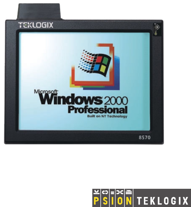
Chapter 1: Introduction Product Features Super VGA TFT Display Touch Screen Figure 1.1 8570 Front (Freezer/Extreme Temperature Version shown) Power Button Display Backlight Dimmer B Figure 1.
Chapter 1: Introduction Product Features PCMCIA Card Slots Product Safety Label Power Connector Ethernet COM1 COM2 Keyboard /Mouse Multimedia Cable Cover Cable Gasket USB Ports Mounting Holes Figure 1.
Chapter 1: Introduction The 8570 Accessories 1.4 The 8570 Accessories The 8570 Vehicle-Mount Computer supports a wide range of peripheral accessories: keyboard, CD ROM Kit, USB Floppy, scanners, and any standard serial or USB peripherals. The following is a list of accessories and their part numbers. For detailed information, please refer to Chapter 3: Operating Information. Peripheral Accessories • External Keyboard: DB9 backlit unit. • External Keyboard: PS/2 backlit unit.
Chapter 1: Introduction The 8570 Accessories Mounting Options • • • • • 8570 Dual Ball and Socket Mounting Kit 8570 & Keyboard Dual Ball and Socket Mounting Kit 8570 Mounting Bracket to Ball Mount or Pedestal Mount 8570 Keyboard Bracket 3" Clamp Base for Universal Dual Ball and Socket Mount PN 31624 PN 31624-001 PN 31658 PN 31596 PN 31625 • 4" Clamp Base for Universal Dual Ball and Socket Mount PN 31625-001 • Universal Dual Ball and Socket Mount PN 31623 Pedestal Mounts • 12" Pedestal mount PN 30921-
Chapter 1: Introduction The 8570 Accessories Power Options • DC/DC Pre-Regulator 10-55 volts range, use for 12 volt nom. trucks that require isolation PN 19893-400 • DC/DC Pre-Regulator* 55- 90 volts PN 19893 • Transient Suppressor PN 19893-500 • Active Transient Filter Power Supply* 15-55 volts PN 19893-600 • AC Power Supply PN 19894 • Extension Power Cable PN 13985 • Cart Battery and 8871 Cart Battery Charger Model# 8870 *Required on forklift trucks.
2 GETTING STARTED 2.1 Unpacking The Box . . 2.1.1 Item Checklist . . 2.1.2 Standard Features 2.1.3 Optional Features . . . . . . . . . . . . . . . . . . . . . . . . . . . . . . . . . . . . . . . . . . . . . . . . . . . . . . . . . . . . . . . . . . . . . . . . . . . . . . . . . . . . . . . . . . . . . . . . . . . . . . . . . . . . .13 .13 .14 .15 2.2 Parts And Controls Of The 8570 . . . . . . 2.2.1 The Front Of The Computer . . . . . 2.2.1.1 Display/Touch Screen. . . . 2.2.
Chapter 2: Getting Started Unpacking The Box 2.1 Unpacking The Box Please take the time to read this chapter thoroughly to familiarize yourself with the operation and use of your Teklogix 8570 Vehicle-Mount Computer. 2.1.1 Item Checklist Check to make sure that all of the following items* were shipped with your 8570 Vehicle-Mount Computer: • • • The Teklogix 8570 Vehicle-Mount Computer. Power Cable PN 31619 (attached to the 8570).
Chapter 2: Getting Started Standard Features 2.1.2 Standard Features FEATURE DESCRIPTION 8570 Computer Casing Processor Operating System Display Digitizer/Digitizing Device Graphic Controller Hard Disk Drive RAM Memory Cache Chipset PC Card Compartments (PCMCIA 2.1) Rugged, IP66 sealed computer with rear cable cover. 30.5 x 24 x 6.1 cm (12 x 9.4 x 2.4 inches), weight: 3.7 kg (7.7 lb.). Intel Mobile Pentium 266MMX. • Windows 98 (English). • Phoenix IBM PC/AT “Plug and Play” compatible BIOS.
Chapter 2: Getting Started Optional Features 2.1.3 Optional Features OPTION DESCRIPTION Scanners Operating System PowerScan decoded tethered scanners. The following operating systems are also available: • WIN2000 (NT-5): English • WIN XP: English Additional languages (WIN98 2nd Edition and WIN2000): Chinese simplified / French / German / Spanish Keyboard External backlit IBM PC/AT-compatible keyboard (Nema 4). PS/2 or DB-9 pin connector.
Chapter 2: Getting Started Parts And Controls Of The 8570 2.2 Parts And Controls Of The 8570 2.2.1 The Front Of The Computer Super VGA TFT Display Touch Screen 2.2.1.1 Display/Touch Screen The 12.1-inch high resolution colour display incorporates a backlit touch screen. The standard resolution for the 8570 is 800 x 600. The display has a 120-degree viewing angle and a backlight which is 0-100% dimmable, using the two buttons located on the side of the computer (see page 17).
Chapter 2: Getting Started Side Buttons 2.2.2 Side Buttons Power Button 2.2.2.1 Dimmer Buttons Power Button The power switch is located on the right side of the computer. Depressing this switch for approximately one second will turn the computer ON. If the switch is held down for more than seven seconds, the computer will power OFF and the hardware will reset fully. Note: When the 500 MHz 8570 Vehicle-Mount Computer is first supplied with power, the unit will power up automatically.
Chapter 2: Getting Started Ports 2.2.3 Ports PCMCIA Card Slots Power Connector Ethernet COM1 COM2 Keyboard /Mouse Multimedia USB Ports Cable Gasket Cable Cover Mounting Holes Figure 2.1 8570 Ports 2.2.3.1 PCMCIA Card Slots There are two PCMCIA card slots located in the top of the computer. These can be used to install additional serial ports, hard drives, LAN cards, or you can plug in a PC card radio for wireless communications. PC Card Covers There are three covers for the PC card slots.
Chapter 2: Getting Started Ports 2.2.3.2 Power Connector The three-pin power receptacle in the 8570 connects to the PN 31619 power cable. The power cable is passed through the cable gasket and is then connected to any of the Teklogix power accessories (see “Using The Power Adaptor” on page 21). 2.2.3.3 Ethernet Port The ethernet port is a 10Base-T/100Base-TX LAN interface, with an RJ45 connector. Warning: 2.2.3.
Chapter 2: Getting Started Precautions 2.2.3.6 Multimedia Port The multimedia port is SoundBlaster 16-compatible. If you purchased multimedia cable PN 31618 with the 8570, connect it to the SoundBlaster-compatible multimedia port (see Figure 2.1 on page 18). The multimedia cable has a Dsub9 connector and three stereo audio connections: Line In, Line Out, and Mic (input). Connect your speakers to the correct port on the end of the cable. The speakers must be amplified. 2.2.3.
Chapter 2: Getting Started Handling Your 8570 Vehicle-Mount Computer 2.3.2 Handling Your 8570 Vehicle-Mount Computer • Do not use sharp objects, such as regular pens, pencils, tools, etc., on the touch screen as they may damage its surface and impair display visibility, or cause it to be inoperable. • Do not poke at the cable gasket, or the water seal will be compromised. • Do not misplace the cable gasket inserts, or the computer seal will be compromised.
Chapter 2: Getting Started Connecting Accessories Important: If peripherals are connected to the 8570, the IP66 cover must be removed. The cables for the peripheral(s) are then placed through the blue cable gasket. For detailed instructions, refer to “Connecting Cables” on page 29. 3. Connect the power cable to the power source, and to the power connector (for detailed instructions, see “Power Options” on page 60). 4. Turn on your 8570 by pressing the power button.
3 OPERATING INFORMATION 3.1 Processor . . . . . . . . . . . . . . . . . . . . . . . . . . . . . . . . . . . .25 3.2 Hard Disk Drive . . . . . . . . . . . . . . . . . . . . . . . . . . . . . . . .25 3.3 Memory. . . . . . . . . . . . . . . . . . . . . . . . . . . . . . . . . . . . .25 3.4 Touch Screen Display . . . . . . . . . . . 3.4.1 TFT Monitor . . . . . . . . . . . . . 3.4.1.1 Backlight Dimmer Buttons . 3.4.2 Touch Screen . . . . . . . . . . . . . 3.4.3 My-T-Soft Onscreen Keyboard . . . 3.4.
3.7.7 Multimedia Cable. . . . . . . . . . . . . . . . . . . . . . . . . . . . 38 3.7.8 Mounting Options . . . . . . . . . . . . . . . . . . . . . . . . . . . 38 3.7.9 Antennas . . . . . . . . . . . . . . . . . . . . . . . . . . . . . . . . 39 3.8 Installing Software . . . . . . . . . . . . . . . . . . . . . . . . . . . . . . 39 3.9 The BIOS Firmware. . . . . . . . . . . . . . . . . . . . . . . . . . . . . . 39 3.10 Typical Resource Allocation For Windows 98. . . . . . . . . . . . . . . . 40 3.
Chapter 3: Operating Information Processor This chapter describes the 8570 Vehicle-Mount Computer in detail and explains each hardware feature. 3.1 Processor The 8570 Vehicle-Mount Computer provides processing power capable of operating today's commercial-off-the-shelf software as well as custom applications written for the MS-DOS and Windows operating systems. The 8570 is equipped with an Intel Mobile Pentium 266 MHz* MMX processor.
Chapter 3: Operating Information Touch Screen Display 3.4 Touch Screen Display 3.4.1 TFT Monitor The 8570 Vehicle-Mount Computer is equipped with a high-resolution colour SVGA display, which supports the newest technology and enables full use of the display both in graphics and in text mode. The TFT 30.7 cm (12.1 in.) display provides a resolution of 800 pixels by 600 pixels and supports 256 colour mode. The colour monitor is a thin film transistor (TFT), which uses a backlight for viewing.
Chapter 3: Operating Information Touch Screen 3.4.2 Touch Screen The 8570 digitizer (touch screen) has a backing made of hardened glass, which provides clarity and strength. The digitizer matrix uses resistive pressure-sensitive technology to deliver X and Y coordinates to the applications and programs that run on the 8570 Vehicle-Mount Computer. The touch screen is responsive to both finger touch and stylus.
Chapter 3: Operating Information Touch Right Onscreen Mouse My-T-Soft can be used for secure applications, network logons, password entry, and various other controlled-input situations. It is also a very useful tool for macros and Windows commands. My-T-Soft has twelve screen sizes and its options panels can expand and retract dependent upon your requirements. To access the program in Windows 98, go to the My-T-Soft menus in the Windows Start/Programs menu.
Chapter 3: Operating Information Ports 3.5 Ports There are eight connectors on the back of the 8570, which can be used for the addition of a variety of peripheral accessories. These connectors are protected from harsh environments by an IP66 cable cover and gasket. The connector locations and gasket arrangement are shown in Figure 3.5 on page 31. In addition, there are two PCMCIA slots on the top of the computer that are available for PC card devices. Specific accessories are described in section 3.
Chapter 3: Operating Information Connecting Cables Important: If the computer is used in a high-moisture environment, it is recommended that natural lubricating grease (PN 98083) be applied prior to re-installing the cable cover. Apply the lubricant around the cables where they pass through the blue cable sealing gasket, and between the cable gasket halves. As well, Nyogel connector lubricant (PN 95146) should be applied to all connectors.
Chapter 3: Operating Information Connecting Cables Metal Dome Cover (with Antenna Connector) PC Card Lid Mounting Holes IP66 Cover with Gasket Cable Gasket Screw USB2 USB1 Multimedia Keyboard /Mouse Cable Gasket COM2 COM1 Ethernet Power Figure 3.
Chapter 3: Operating Information Power 3.5.2 Power The 8570 Vehicle-Mount Computer can be connected to either an AC or DC power supply, depending on whether its use is for mounting on vehicles or at fixed locations adjacent to cross-dock doors or manufacturing stations. Power is supplied to your 8570 computer through the power connector (see Figure 3.5 on page 31). Note: When the 500 MHz 8570 Vehicle-Mount Computer is first supplied with power, the unit will power up automatically.
Chapter 3: Operating Information Ethernet Port 3.5.3 Ethernet Port Warning: The USB and ethernet ports are not to be used for typical end user applications and installations. These ports are designed to be used for maintenance and setup purposes only. They should only be used for temporary service connections required for file transfers, set up, configuration, etc. The Ethernet on the 8570 Vehicle-Mount Computer is integrated within the unit and provides the LAN interface.
Chapter 3: Operating Information Multimedia Port 3.5.6 Multimedia Port The multimedia (sound) port is a Dsub9 female with key pin connector. The multimedia port on the computer provides stereo connections for line input, microphone input, and line output, which is used for external amplified speakers. The sound components of the 8570 Vehicle-Mount Computer enable you to record, compress, as well as play back voices, sound and music. Volume control can be achieved onscreen through the built-in mixer.
Chapter 3: Operating Information 8570 Vehicle-Mount Computer: Freezer Version If either the Lucent/Agere 802.11b or the Cisco Air350 802.11b PC card radio* have not been installed, then both Type II slots are available. When no radio is installed, the PC card slots are covered with a flat lid, rather than a dome cover. However, one PC card slot is usually reserved for the radio, leaving the other slot ready for peripheral cards such as: ATA Flash cards, GPS cards, Nokia Cell phone cards, etc.
Chapter 3: Operating Information Accessories • All LCD computers used in freezers may require some brightness adjustment because displays may darken as the surrounding temperature drops. Adjust the brightness as required. Response time of the display may also slow down. • When moving between a freezer and warm, humid environments, window condensation or icing on the outside of the display window is a natural occurrence.
Chapter 3: Operating Information External Keyboard 3.7.1 External Keyboard The rugged 8570 Keyboard (PN 31612 or 31612-001) is an optional external keyboard, designed specifically for mobile computing applications. The touch screen will still operate when the keyboard is attached to the computer. The external keyboard PN 31612 is a DB9 backlit unit. If both the keyboard and a scanner are to be used together, a PS/2 version of the same keyboard is available (PN 31612-001).
Chapter 3: Operating Information USB Floppy Drive 3.7.6 USB Floppy Drive The bootable floppy drive (PN 31627) connects through the USB port. This drive will also allow administrators to boot from the drive to perform any software maintenance if required. Important: To use the USB floppy boot feature, USB BIOS Legacy Support must be enabled., and the Parallel Port must be disabled in the 8570 BIOS Setup (see “The BIOS Firmware” on page 39).
Chapter 3: Operating Information Antennas 3.7.9 Antennas If a PC card radio is installed in one of the 8570 PCMCIA slots, the antenna may be internal or external. When equipped with an antenna, the 8570 has a dome cover on the top left of the computer. The type of dome cover depends on the antenna used: plastic cover for an internal antenna, and a metal cover for an external antenna. For a description of available antennas, please see page 59. 3.
Chapter 3: Operating Information Typical Resource Allocation For Windows 98 6. Then go to the Advanced Menu of the BIOS and set the following values: Reset Configuration Data = Yes In the I/O Device Configuration Sub-menu: Serial port A = Auto Serial port B = Auto IRDA = Disabled Parallel port = Disabled USB Host Controller = Enabled USB BIOS Legacy Support = Enabled 7. Press to save and restart.
Chapter 3: Operating Information Typical Resource Allocation For Windows 98 IRQ Device 0 1 2 3 4 5 6 7 8 9 10 11 12 13 14 15 TIMER 0 KEYBOARD SLAVE 8259 COM2 COM1 FDC LPT1 RTC PS/2 MOUSE FPU IDE0 IDE1 Available Comment No No No No No Yes Yes No No Yes Yes Yes No No No No Note* Note* Note* Note* Note* Note* Note* *Note: If a device is disabled in setup, the corresponding interrupt is available for other devices. Table 3.
Chapter 3: Operating Information Backing Up Your 8570 Vehicle-Mount Computer DMA Device 0 1 2 3 4 5 6 7 Available FDC CASCADE Comment Yes Yes No Yes No Yes Yes Yes Table 3.2 Typical Resource Allocations - DMAs Upper Memory C0000h-CBFFF h CC000h-DFFFF h E0000h-EFFFF h F0000h-EC000h Device VGA BIOS SYSTEM BIOS Available Comment No Yes ISA bus or shallow RAM Yes ISA bus only No Table 3.3 Typical Resource Allocations - Memory 3.
Chapter 3: Operating Information Backing Up Your 8570 Vehicle-Mount Computer Methods of backing up data include: • Copying your data to a network server or another networked computer. • Copying your data to a CD-ROM drive to create a permanent, incorruptible archive. • Copying your data to a backup device such as a tape drive or to an external hard drive. Important: A Microsoft Windows licensed registration number is affixed under the port cover of each 8570 unit.
4 INSTALLATION 4.1 Mounting Accessories . . . . . . . . . . . . . 4.1.1 8570 Mounting Brackets . . . . . . . . . 4.1.2 Security Mounting Options . . . . . . . 4.1.3 Standard Mounting Options . . . . . . . 4.1.4 8570 With Keyboard Mounting Brackets 4.1.5 Pedestal Mounts . . . . . . . . . . . . . . . . . . . . . . . . . . . . . . . . . . . . . . . . . . . . . . . . . . . . . . . . . . . . . . . . . . . . . . . . . . . . . . . . . . . . . . . . . . . . . . . . . . . . . . . .47 .47 .48 .48 .
Chapter 4: Installation Mounting Accessories 4.1 Mounting Accessories The 8570 Vehicle-Mount Computer is equipped with four mounting holes on the bottom surface of the computer to permit attachment of either the 8570 Mounting Bracket or Quick-Release Bracket for fixed mounting to a variety of vehiclemounting systems for forklift trucks, push carts, hostling vehicles and transtainers. As well, the 8570 can be mounted at fixed locations adjacent to cross-dock doors or manufacturing stations.
Chapter 4: Installation Security Mounting Options 4.1.2 Security Mounting Options Security mount kits are designed to prevent the 8570 computer from being removed from the mount without a special tool. • 8570 Universal Dual Ball and Socket Mount Security Kit PN 1000398-570 This kit includes a clamp with security hardware and a special Philips bit and hex socket.
Chapter 4: Installation 8570 With Keyboard Mounting Brackets • 3" Clamp Base for Universal Dual Ball and Socket Mount The clamp base is available in a 3" or 4" clamp size. This clamp base with ball attaches to one end of the Universal Dual Ball and Socket Mount (31623). It can be used to mount the 8570 on the overhead cross-bars on a forklift or any similar surface. PN 31625 • 4" Clamp Base for Universal Dual Ball and Socket Mount PN 31625-001 (see description for 3" Clamp Base, above).
Chapter 4: Installation Pedestal Mounts • Keyboard Quick-Release Bracket The optional keyboard is attached to this quick-release bracket (3 pieces in total). The unit is then mounted directly to the surface of a cantilever mount (17293), a full-width mount (17280), or directly to the dash or other appropriate surface of the vehicle. PN 30876-401 4.1.
Chapter 4: Installation Handling Your 8570 Vehicle-Mount Computer 4.2.2 Handling Your 8570 Vehicle-Mount Computer • Do not use sharp objects, such as regular pens, pencils, tools, etc., on the touch screen as they may damage its surface and impair display visibility, or cause it to be inoperable. • Do not poke at the cable gasket, or the water seal will be compromised. • Do not misplace the cable gasket inserts, or the computer seal will be compromised.
Chapter 4: Installation Mounting The 8570 4.2.4 Mounting The 8570 A typical installation includes: 1. Mounting the computer (refer to “Mounting The 8570” on page 52). 2. Connecting the external antenna, if applicable (refer to “External Antennas” on page 59). 3. Installing the power accessories (refer to “Power Options” on page 60). Notes: 1. Make sure that the unit is mounted inside the roll cage of the vehicle. 2. The bolts used for all installations are SAE 1/4-20. 4.2.4.
Chapter 4: Installation Mounting The 8570 Stylus Clips Mounting holes Figure 4.2 Mounting Bracket (PN 31658) PN 31623 (Universal Dual Ball/Socket Mount) PN 31658 (8570 Mounting Bracket) PN 31596 (Keyboard Bracket) Figure 4.
Chapter 4: Installation Mounting The 8570 4.2.4.2 Installing The Quick-Release Bracket Assembling The Bracket To construct the 8570 Quick-Release Bracket (PN 30876-400), carefully attach the 8570 to the mounting bracket provided in the kit, and then to the mounting cradle, as shown in Figure 4.4. Place the computer in the cradle so that the top of the display is on the same side as the tabs of the cradle. The computer connectors should be on the same side as the quick-release fasteners.
Chapter 4: Installation Mounting The 8570 Installing The Cradle Mounting Plate Next, the cradle mounting plate is usually attached directly to the vehicle, but the Cantilevered Mount Kit (PN 17293) or a Full-width Mount (PN 17280) can also be used. The cradle mounting plate shown in Figure 4.5 holds the computer and cradle in place on the vehicle or on either of these vehicle mounts.
Chapter 4: Installation Mounting The 8570 Attaching The Cradle To The Cradle Mounting Plate Next, the 8570 with cradle must be attached to the cradle mounting plate. • Align the tabs on the rear of the cradle to the tab guides on the mounting plate and push the cradle back and down. • Slide the fasteners on the front of the cradle until they snap to the posts on the mounting plate. Warning: 4.2.4.3 Never operate the vehicle if the quick-release fasteners are not locked.
Chapter 4: Installation Installing Security Mount Options 4.2.5 Installing Security Mount Options 4.2.5.1 Attaching Dual Ball Socket Security Mounts – PN 1000398 Security Brackets Rubber strips for Security Brackets Security Screws Figure 4.7 Dual Ball Socket Security Mount Kit • Place the rubber strips inside the security brackets. • Use the security screws included with your kit to attach the security brackets to the dual ball socket mount.
Chapter 4: Installation Installing Security Mount Options • Mount the 8570 to the mounting plate (PN 31658) using four security screws (PN 9000049). Note: If you are using an external keyboard, sandwich the keyboard bracket (PN 31596) between the mounting plate (PN 31658) and the dual ball socket mount. Use security screws (PN 9002011) to attach the three pieces. Then you can go ahead and mount the 8570 to the mounting plate. 4.2.5.
Chapter 4: Installation Installing Cables 4.2.6 Installing Cables For detailed instructions on connecting cables to the 8570, please refer to “Connecting Cables” on page 29. When installing the cables between the computer and other devices, consider the following: • • • • • • • Ensure the vehicle body and underlying wiring is not damaged while drilling mounting holes. Protect cable runs from pinching, overheating and physical damage. Protect cables by using grommets when cables pass through metal.
Chapter 4: Installation Power Options The external antennas consist of a 2.4 GHz Magmount antenna (PN 97583) and a 2.4 GHz 2 DBI Omni Articulating antenna (PN 96302). The antennas connect to the proprietary SMA-type connector on the metal dome cover of the computer. Turn the antennas in a counter-clockwise direction. The magmount antenna works best when placed vertically and away from metal objects that may interfere with the radio signal.
Chapter 4: Installation Power Options 4.2.8.1 Non-Vehicle Installation Using AC power, the 8570 Vehicle-Mount Computer can be mounted at fixed locations adjacent to cross-dock doors, manufacturing stations, or in offices. The universal 120/240 VAC power supply (PN 19894) should be used to power the computer from an AC source. 4.2.8.2 Installing The Pre-regulator The Pre-regulator should be used on all vehicles that run off voltages greater than 12 VDC nom.
Chapter 4: Installation Power Options Note: Transient Suppressor Keep in mind that this transient suppressor is not required on 24-48V trucks if the Active Filter Power supply (PN 19893-600) is installed. On 12 V trucks, the Transient Suppressor (PN 19893-500) can be installed between the vehicle battery and the computer (or between the battery, pre-regulator and the computer) to reduce high voltage spikes from a power supply.
Chapter 4: Installation Power Options 4.2.8.3 Installing The Active Transient Filter Power Supply The Active Transient Filter Power Supply (PN 19893-600) is designed to filter out large volumes of transients and surges. It can be used to power both standard temp. and freezer 8570 vehicle-mount computers. Note: The -600 must be installed on all 24-48 VDC battery powered trucks. Figure 4.
5 MAINTENANCE 5.1 Introduction. . . . . . . . . . . . . . . . . . . . . . 5.2 Maintenance . . . . . . . . . . . . . . . . . . . . . 5.2.1 Important Safeguards . . . . . . . . . . . . . 5.2.2 Handling Your 8570 Vehicle-Mount Computer 5.3 Inspection. . . . . . . . . . . . . . . . . . . . . . . 5.4 Cleaning . . . . . . . . . . . . . . . . . . . . . . . 5.4.1 Display . . . . . . . . . . . . . . . . . . . . . 5.4.2 Housings . . . . . . . . . . . . . . . . . . . . 5.4.3 Optional Keyboard . . . . . . . . . . . .
Chapter 5: Maintenance Introduction 5.1 Introduction This chapter describes how to maintain, inspect and clean your 8570 Vehicle-Mount Computers. These instructions are intended to identify the cleaners, tools, and actions required by 8570 users to clean the LCD (liquid-crystal display) screen and computer housings. 5.2 Maintenance 5.2.1 Important Safeguards • To avoid possible injury, this device must be properly secured when in a moving vehicle. • Keep this device away from magnetic fields.
Chapter 5: Maintenance Inspection 5.3 Inspection At least weekly, or more frequently if the user environment warrants, visually inspect the computer for missing or damaged items: • PCMCIA cover. • Loose or missing screws. • Damaged cables. • Loose connections. • Compromised cable gasket seal. Report damaged or missing items immediately and repair the computer prior to reassigning it. 5.4 Cleaning The 8570 is maintenance-free, except for normal cleaning.
Chapter 5: Maintenance Housings 5.4.2 Housings Using a soft, lint-free cloth, try to regularly keep the 8570 clean and free from dust and dirt. If available, you can also use compressed air, but some caution is to be observed. Important: DO NOT use full strength liquid household detergents, solvents, or other chemicals such as benzine, gasoline, kerosene, thinners or chemical cloths to clean your equipment. 5.4.3 Optional Keyboard Spray a mild all-purpose cleaner onto a cloth and gently wipe the surface.
6 TROUBLESHOOTING 6.1 Introduction. . . . . . . . . . . . . . . . . . . . . 6.2 Preventive Measures . . . . . . . . . . . . . . . . 6.3 Problems . . . . . . . . . . . . . . . . . . . . . . 6.3.1 Display . . . . . . . . . . . . . . . . . . . . 6.3.2 Hard Drive . . . . . . . . . . . . . . . . . . 6.3.3 Optional Keyboard . . . . . . . . . . . . . . 6.3.4 PCMCIA . . . . . . . . . . . . . . . . . . . 6.3.5 Power. . . . . . . . . . . . . . . . . . . . . 6.3.6 I/O Ports . . . . . . . . . . . . . . . . . . . 6.
Chapter 6: Troubleshooting Introduction 6.1 Introduction This chapter provides information on the recognition and correction of problems that you may encounter when operating the 8570 Vehicle-Mount Computer. If problems are encountered that are not identified here or that can’t be resolved, please refer to Appendix A: “Support Services And Worldwide Offices” for contact information. 6.2 Preventive Measures • • • • • • • • • • • Check that the computer is connected to a working power source.
Chapter 6: Troubleshooting Problems 6.3 Problems 6.3.1 Display No Backlight • Boot the unit and increase the brightness control. • Make sure that Suspend is off. No Video • Verify that the backlight is on, adjust up. • Check that there’s power to the unit. • Verify with a keyboard that the Num Lock LED works. • Make sure that Suspend is off. Display Quality Poor • Clean the screen. • Adjust the brightness. • Verify with a keyboard that the Num Lock LED works. 6.3.
Chapter 6: Troubleshooting Optional Keyboard Time Or Date Incorrect • Correct the time and/or date in the Windows program. If the problem persists, the lithium battery may need to be replaced by Psion Teklogix. Beep Codes If beep codes are being received, the computer should be serviced by Psion Teklogix. 6.3.3 Optional Keyboard • If the keyboard has stopped responding, check that the application has not disabled the keyboard. • Press and hold any key.
Chapter 6: Troubleshooting I/O Ports DC Power Source • Inspect the fuse in the DC power cable. If the fuse is blown, replace it with an equivalent value. If fuses are blown repeatedly, the computer or pre-regulator should be serviced. 6.3.6 I/O Ports • Verify that the BIOS setup for I/O is correct (see “Typical Resource Allocation For Windows 98” on page 40). • Make sure that the PCMCIA card and the I/O are not conflicting. 6.
Chapter 6: Troubleshooting Software Loading/Installation Procedure 6.5 Software Loading/Installation Procedure Important: It is critical that you carry out the instructions listed in the appropriate section below step by step, beginning at step 1. 6.5.1 Computers Using Microsoft Windows 98 1. Load/Install Network/Ethernet driver Go to My computer> update drivers> next> next Browse> Go to D:\driver\network. 2. Load/Install Video Drivers ATI Go to My computer Go to D:\driver\Ati select setup 3.
Chapter 6: Troubleshooting Computers Using Microsoft Windows 2000 6.5.2 Computers Using Microsoft Windows 2000 1. Load/Install Network drivers Go to My computer> Properties> Hardware> device manager Go to Other device> Ethernet controller> properties> drivers Update drivers> next> next Browse to D:\driver\network 2. Load/Install Touch Screen Run the touch screen install utility located in the drivers directory on the D drive.
7 SPECIFICATIONS 7.1 8570 Hardware Specifications . . . . . . . . . . . . . . . . 7.1.1 Physical . . . . . . . . . . . . . . . . . . . . . . . . 7.1.2 Environmental Characteristics . . . . . . . . . . . . . 7.1.3 Standard Display . . . . . . . . . . . . . . . . . . . . 7.1.4 Power Requirements . . . . . . . . . . . . . . . . . . 7.1.5 Standard Processor And Memory . . . . . . . . . . . 7.1.6 PC Radio Cards . . . . . . . . . . . . . . . . . . . . 7.1.7 Network Interface . . . . . . . . . . . . . . . . . . .
Chapter 7: Specifications 8570 Hardware Specifications 7.1 8570 Hardware Specifications 7.1.1 Physical Enclosure 2-piece precision-milled, powder-coated aluminum for major mechanical housing and components, with high-impact strength at high and low temperature extremes, and resistance to common chemicals. Dimensions 30.5 x 24 x 6.1 cm (12 x 9.4 x 2.4 inches) Weight 3.7 kg (7.7 lb.) 7.1.
Chapter 7: Specifications Environmental Characteristics 8570 Standard Temperature Temperature Operating High +60°C (+140°F) Low -20°C (- 4°F) Storage High +75°C (+167°F) Low - 30°C (-22°F) Relative Humidity Operating 5% to 96% non-condensing. 8570 Freezer/Extreme Temperature Temperature Operating High +60°C (+140°F) Low - 35°C (-31°F) Storage High +75°C (+167°F) Low - 30°C (-22°F)* *Ideally, store computer above 0°C (32°F). Relative Humidity Operating 5% to 96% condensing.
Chapter 7: Specifications Standard Display 7.1.3 Standard Display High Bright TFT-screen, 30.7 cm (12.1") SVGA. 800x600 pixels/256k colours. 120˚ viewing angle. 500 NIT brightness, 0-100% dimmable. High-transparency resistive digitizer with hardened glass. 7.1.4 Power Requirements DC Power AC Power 9-36 VDC 5W standby/20W operating, max 32W. Input Voltage Ranges: 100-127 VAC, 200-240 VAC Frequency: 47-63 Hz 7.1.
Chapter 7: Specifications Network Interface Cisco Air350 802.11b DS SS (TRX7441)* Transmit Power 1, 5, 20, 30, 50, 100mW Maximum power setting will vary according to individual country regulations. Frequency Range Channels 2.4 GHz - 2.5 GHz 11 (FCC) 13 (ET) 14 (JP) 2 (SP) 4 (FR) 1, 2, 5.5, 11Mbps Data Rates * For regulatory information concerning the Cisco Air 350 PC Card, please see page 89. Also refer to the “Cisco End User License Agreement” on page ix. 7.1.
Chapter 7: Specifications 8570 External Keyboard Option 7.3 8570 External Keyboard Option 7.3.1 Industrial Ratings NEMA 4 UL-1950 CE FCC Class 15, Part B 7.3.2 Physical Enclosure Dimensions ABS-Polycarbonate plastic case 28.9 x 16.0 x 4.7 cm (11.4 x 6.3 x 1.86 inches) Key Switch: Material Life Travel Actuation Force Feedback Industrial silicone rubber Greater than 10 million cycles 1.5 mm (0.060 in.) 130g (5 oz.) Tactile with mechanical snap 7.3.
Chapter 7: Specifications Power 7.3.4 Power Keyboard HulaPoint Backlight 5V@10ma (from CPU port) 5V@10ma (from mouse conn. port) 5V@200ma (from CPU port) 7.3.5 Cable Length Design 1.2 m (4 ft.) coiled “Y” Cable (providing separate keyboard and mouse connections) 7.3.6 Compatibility Keyboard HulaPoint PS/2, AT, Windows, and NT Microsoft, PS/2, Serial, and Logitech 7.3.7 Backlighting Four levels of backlighting (including Off). Low ma green LEDs. Operates from key on keyboard.
Chapter 7: Specifications Regulatory Information: Lucent/Agere WaveLAN PC Card 7.4 Regulatory Information: Lucent/Agere WaveLAN PC Card The IEEE 802.11 WaveLAN PC Card must be installed and used in strict accordance with the manufacturer’s instructions. This device complies with the following radio frequency and safety standards. Canada - Industry Canada (IC) This device complies with RSS 210 of Industry Canada.
Chapter 7: Specifications Regulatory Information: Lucent/Agere WaveLAN PC Card USA - Federal Communications Commission (FCC) This device complies with Part 15 of FCC Rules. Operation of the devices in a WaveLAN System is subject to the following two conditions: • This device may not cause harmful interference. • This device must accept any interference that may cause undesired operation. Important: Exposure to Radio Frequency Radiation. The radiated output power of the IEEE 802.
Chapter 7: Specifications Regulatory Information: Cisco Air350 PC Card If this equipment does cause harmful interference to radio or television reception, which can be determined by turning the equipment off and on, the user is encouraged to try and correct the interference by one or more of the following measures: • Reorient or relocate the receiving antenna. • Increase the distance between the equipment and the receiver.
Chapter 7: Specifications Regulatory Information: Cisco Air350 PC Card USA – Federal Communications Commission (FCC) This equipment generates and may radiate radio-frequency energy. If it is not installed in accordance with Cisco installation instruction, it may cause interference with radio and television reception. This equipment has been tested and found to comply with the limits for Class B digital device, pursuant to part 15 of FCC rules.
APPENDIX A SUPPORT SERVICES AND WORLDWIDE OFFICES A.1 Support Services Psion Teklogix provides a complete range of product support services to its customers worldwide. These services include post-installation technical support and product repairs. A.1.1 Canada and U.S.A: Technical Support and Repair Services In Canada and the U.S.A. these services can be accessed through the Psion Teklogix Helpdesk.
A.2 WORLDWIDE OFFICES COMPANY HEADQUARTERS AND CANADIAN SERVICE CENTRE NORTH AMERICAN HEADQUARTERS AND U.S. SERVICE CENTRE Psion Teklogix Inc. 2100 Meadowvale Boulevard Mississauga Ontario Canada L5N 7J9 Tel: +1 905 813 9900 Fax: +1 905 812 6300 E-mail: salescdn@psion.com Psion Teklogix Corp. 1810 Airport Exchange Boulevard Suite 500 Erlanger, Kentucky USA 41018 Tel: +1 859 371 6006 Fax: +1 859 371 6422 E-mail: salesusa@psion.
Psion Teklogix España, S.L. Cityparc Ronda de Dalt Ctra. Hospitalet 147-149 Edificio Atenas 2˚ 3ª 08940 Cornellà de Llobregat (Barcelona) España Tel: +34 9 3475 0220 Fax: +34 9 3475 0230 E-mail: teklogix@apdo.com Psion Teklogix Systems India Pvt. Ltd. M-74, 1st Floor, “M” Block Market Greater Kailash-Il New Delhi - 110048 India Tel: +91 11 621 9257 Fax: +91 11 621 9076 E-mail: tekind@psion.
APPENDIX B THE 8570 KEYBOARD B.1 Keyboard Features The 8570 Keyboard (PN 31612) is an external DB9 QWERTY keyboard, designed specifically for mobile computing applications. It is rugged and sealed to resist water, dust, shock and vibration. Designed for in-vehicle or harsh environment use, it is rated Nema 4. The DB9 cable is connected to the 8570 through the cable gasket. For detailed keyboard specifications, please see page 85. A PS/2 version (PN 31612-001) of the same keyboard is also available.
Appendix B: The 8570 Keyboard Keyboard Connection And Maintenance B.2 Keyboard Connection And Maintenance To connect your Teklogix 8570 keyboard safely, please follow these instructions: 1. Turn off the power to your computer. 2. Unplug your existing keyboard (if installed). 3. Plug your new Teklogix 8570 keyboard into the same port. 4. Turn on the power to your computer. The lock keys should flash, confirming proper connection. Your keyboard is ready for use.
Macro Key Windows 98 Start Menu Key HulaPoint “Mouse” Windows 98 Application Key 12 Function Keys compatible with Windows 98 Standard Screen Control Pad Embedded Numeric Keypad Standard Inverted “T” Cursor Pad Keyboard Backlight Key Appendix B: The 8570 Keyboard Installing The Keyboard Figure B.
Appendix B: The 8570 Keyboard Function Keys B.4 Function Keys B.4.1 Accessing The Embedded Numeric Keypad Functions Figure B.3 Numeric Keypad The embedded numeric keypad consists of 16 keys. The numeric keypad and related functions are accessed by depressing the toggle key, which activates the numeric keypad. When the key is on, the LED below is illuminated. B.4.
Appendix B: The 8570 Keyboard Macro Key B.4.4 Macro Key The Macro key is programmed to send a + signal when pressed, and the key will light up for 30 seconds. If your application is configured to recognize this signal, it will respond as if this key sequence was entered. See Figure B.2 on page B-3 for the location of this key. B.4.
APPENDIX C TOUCH SCREEN CALIBRATION Normally calibration is necessary only once since calibration data is stored in the Windows registry files. To calibrate the touch screen in Windows: 1. Start by opening the Control Panel (Figure C.1). Figure C.1 Control Panel 2. Double-click on ‘Pointer Device’ icon to begin calibration. 3. Click on the ‘Calibration’ tab (Figure C.2). Figure C.
Appendix C: Touch Screen Calibration 4. To change the number of calibration points from the default of 5, click on the right or left arrows next to the ‘Calibration points’ option in the screen below (Figure C.3). 5. To adjust calibration timeout – the number of seconds that can elapse without the stylus touching the screen before calibration is cancelled – click on the right or left arrow next to the ‘Timeout’ option on this screen (Figure C.3). Figure C.3 Calibration Screen 6.
Appendix C: Touch Screen Calibration Optional Touch Screen Setting Adjustments • The options under the ‘Settings’ tab allow you to customize how your stylus behaves on the touch screen. The time is measured in increments of 55ms for ‘Click Time’, ‘Tap Time’ and ‘Lift Off Time’. Figure C.5 Settings • The ‘Windows’ tab (Figure C.6) provides options to adjust the stylus double-click – the ‘Time’ between clicks and the acceptable distance in ‘Height’ and ‘Width’ from the item you want to double-click on.
Appendix C: Touch Screen Calibration • To make certain that your touch screen is reading the movement of the stylus accurately, click on the ‘Test’ button at the bottom of the screen (Figure C.7). Figure C.7 Touch Screen Test • Run your stylus up and down the ‘Test’ screen (Figure C.8) in a continuous line, approximating the pattern in the sample test screen below. Do not lift the stylus from the screen.
INDEX A accessories 8, 36 peripheral 8 AC power source 75 supply 61 Active Transient Filter Power Supply 63 anschluß an antennennanlagen x antennas 9, 15, 39 external 59 safety x Appendix 1 audio type 14 B backing up the computer 42 backlight dimmer 26 troubleshooting 74 backlighting 86 beep codes 75 troubleshooting 75 BIOS firmware 39 boot device 15 failure 74 bootable floppy drive 38 bracket, assembling 54 buttons dimmer 17, 26 power 17, 32 C cable gasket 29 lubricating grease 8 cables 86 connecting to
Index D DC power source 76 devices, resource allocation (IRQs) 41 digitizer 14 dimmer buttons 17, 26 location 6 D Install Partition 76 diskette drive see hard disk drive display 14, 16, 68, 74 backlight 74 cleaning 68 maintenance 68 poor quality 74 specifications 83 touch screen 26 troubleshooting 74 DMAs 42 dome covers, plastic and metal 59 DOS virtual keyboard 74 driver, installing 77 driver, loading 77 E electrical vehicles 61 environmental characteristics 81 specifications 81 equipment inspection 68 e
Index install driver 77 partition D 76 software 77 installation Active Transient Filter Power Supply 63 connecting cables to 8570 29 cradle mounting plate 55 external antennas 59 external keyboard 56, B-2 keyboard quick-release bracket 56 non-vehicle 61 pre-regulator power cable (vehicles) 61 quick-release bracket 54 software 39 vehicle 50–62 8570 cables to devices 59 Install Partition, D 76 interface, network 84 IRQs 41 item checklist 13 K keyboard 15, 69, 85, B-1–B-5 cleaning 69, B-2 connection and maint
Index non-vehicle installation 61 numeric keypad functions B-4 accessing B-4 Nyogel connector lubricant 8, 30 O offices list iii, A-3 on-screen keyboard 14, 27 My-T-Soft 27 on-screen mouse Touch Right 28 operating information 23 system 84 systems supported 14, 15 operating system, restoring 76 optional features and accessories 15 keyboard 69, 75 P parts and controls of the 8570 16 PC cards see PCMCIA PCMCIA 75 compartment types 14 PC card slots 18, 34 radio card 83 troubleshooting 75 pedestal mounts 9, 50
Index antenna x enclosure x environment x instructions x summary vii Scan Disk 74 scanner list 37 type 15 SDRAM 83 security mount kits installing dual ball socket security (PN 1000398) 57 QR Security (PN 1000304-570) 58 options 9, 48 serial port 33 service information iii, A-1 side buttons 17 software programs 14 software, installing 77 software,loading 77 sound features 34 specifications 79–89 environmental 81 freezer/extreme temperature 8570 82 keyboard 85 physical 81, 85 power requirements 83 standard di
Index W warranty iii website address A-4 Windows® 98 14, 75 function keys B-4 resource allocation 40–41 worldwide offices iii, A-3 500 MHz viii, 17, 22, 32, 88 802.